Remanufacturing
the Lexmark W812 Toner Cartridges
0303
First introduced in October 2002, the W812 machine is based on
a 26ppm, 1200dpi Fuji-Xerox laser printer engine. This engine is
capable of printing on 11” x 17” paper. The exact engine
number is not known, but if Fuji-Xerox has kept with past practices,
it would be the XP-26 (26ppm). The cartridge itself is very easy
to remanufacture, and with list prices above $200.00USD per cartridge,
a nice profit maker as well. While as of this writing, only the
toner is available. Drums, wiper blades, doctor blades, and seals
are in development. The cartridge is rated for 12,000 pages and
is loaded with 550g of toner. These machines tend to be used as
workgroup printers, so if you have a customer that has one, the
cartridge volume will be on the high side.
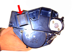
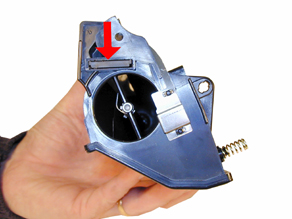
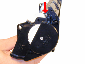
These cartridges have white pins located on each side of the cartridge
that lock the two halves of the cartridge in place. The heads of
the pins have what looks like one way screw heads on them. See Figure
1 We have contacted multiple specialty screw manufacturers to see
if a special tool is available, but were not able to find one. They
can be removed by inserting a 1” long #6 or #8 wood screw
into the center of the pin. You can then twist the pin and pull
it out.
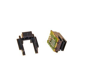
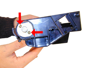
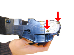
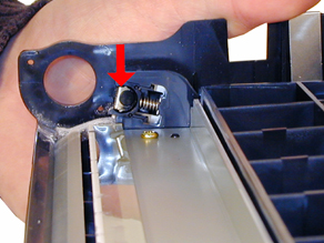
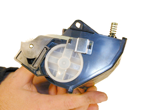
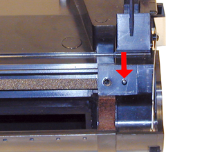
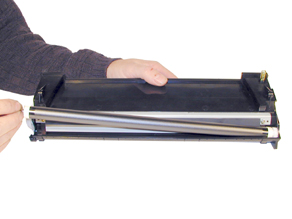
These cartridges also have a chip that tells the machine what brand
of cartridge it is (Lexmark, IBM etc.) and also monitors the toner
low. The housing for the chip consists of two plastic parts, and
the board. See Figure’s 2 & 3. From our initial tests
the cartridge can be recycled at least one time with no issues.
Testing is still ongoing, and we will publish an update when it
is complete.
The machines that are based on the XP-26 engine are as
follows.
Epson LP-8100
Epson LP-8700
IBM InfoPrint 1226
IBM InfoPrint 1226 tn
Lexmark W812
Lexmark W812 tn
Lexmark W812 dtn
Printer error codes as well as how to run test prints will be discussed
at the end of this article.
- 550g XP-26 toner.
- New drum (Check for availability)
- New Wiper Blade (Check for availability)
- Sealing Strip (Check for availability)
- Cotton Swabs
- Isopropyl Alcohol
- Drum Padding Powder
- Conductive Grease
- Dedicated Magnetic Roller Cleaner
- Phillips head screw driver.
- Small Common screwdriver
- Needle Nose pliers
- Spring Hook
- Vacuum approved for toner
Orient the cartridge so that the handle is towards you (Spring
on the right).
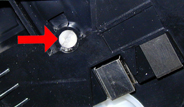
1) On either side of the cartridge is a white plastic pin with
one way screw heads. These pins are what holds and locks both halves
together. Specialty drivers to remove them are not available, so
the only way as of now to remove them is to insert a 1” long
# or #8 wood screw into the center of the pin. Rotate the pin, and
pull out to remove. Leave the screws in so they can easily be installed.
See Figures 4, 5 & 6
|
|
Figure
1 |
Figure 2 |
|
|
Figure
3 |
Figure 4 |
|
|
Figure
5 |
Figure 6 |
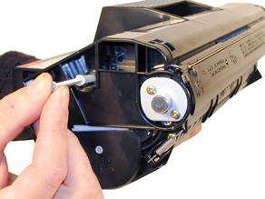
2) Remove the spring from the right side of the cartridge. See
Figure 7
3) Remove the two screws and metal drum axle pin from the black
gear side of the drum. See Figure 8
4) Remove the two screws and white plastic drum axle pin from the
white gear side of the drum. See Figure 9
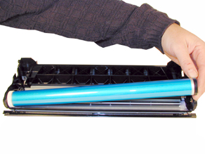
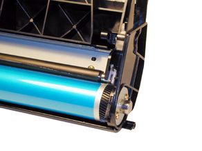
5) Remove the drum. See Figure 10
|
|
Figure
7 |
Figure 8 |
|
|
Figure
9 |
Figure 10 |
6) Remove the PCR from its holders. See Figure 11
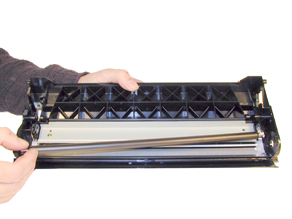
7) Remove the two screws and wiper blade. See Figure 12
8) Clean out the waste chamber. Be very careful not to lose or
damage the foam wiper blade seal. This seal is very fragile and
a vacuum/compressed air cleaning system will damage it if you are
not careful. Note that the waste chamber is very small for this
size cartridge. This is the first Fuji-Xerox system I have seen
that is efficient in the use of toner. See Figure 13
9) Coat the wiper blade with your preferred lubricant, and install
in the cartridge. Install the two long screws the four short screws
are for the drum axle pins only. See Figure 14
|
|
Figure
11 |
Figure 12 |
|
|
Figure
13 |
Figure 14 |
10) Clean the PCR contacts with a cotton swab and alcohol. See
Figure 15
11) Clean the PCR with your preferred PCR cleaner, and install
in the holders. See Figure 16
12) Install the drum, axle pins, and screws. Make sure that the
metal axle pin is on the black gear side, and the white plastic
pin is on the white gear side. See Figures 17 & 18.
|
|
Figure
15 |
Figure 16 |
|
|
Figure
17 |
Figure 18 |
13) Although the toner hopper can be cleaned and filled through
the fill plug, it is recommended that the magnetic roller be removed
and cleaned. This will also be necessary to do once a seal is available.
14) With the pair of needle nose pliers, pull the fill plug out.
Grasp the plug by the cross braces, and pull. This method does not
damage the plug seal. Be careful not to damage the contact that
over hangs the fill plug. It does not have to be removed, just be
careful. Dump out any remaining toner from the hopper. See Figure
19
15) On the side opposite the fill plug, Remove the two screws and
end cap. See Figure 20
16) With the keyed shaft of the magnetic roller free, lift up on
the keyed end. Pull the entire magnetic roller assembly free. See
Figure 21
17) Remove the two screws and doctor blade. Clean out any remaining
toner. See Figure 22
|
|
Figure
19 |
Figure 20 |
|
|
Figure
21 |
Figure 22 |
18) When a seal is available, it should be installed now. Make
sure the seal tab is slid into the seal tab slot. See Figure 23
19) Install the cleaned doctor blade and two screws. Be careful
not to damage the alignment pins. See Figure 24
20) Clean the magnetic roller assembly with a dedicated magnetic
roller cleaner. Install the assembly left side (round shaft) first.
Keep the flat side of the keyed shaft facing the gears. See Figure’s
25 & 26
|
|
Figure
23 |
Figure 24 |
|
|
|
Figure 25 |
Figure 26 |
21) Install the end cap, make sure the keyed end of the magnetic
roller is in its slot. The gear posts must also align to the end
cap holes. Install the two screws. See Figure 27
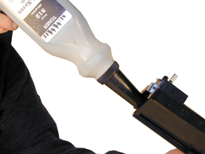
22) Fill with 550g XP-26 toner. See Figure 28
23) Install the fill plug, check for leaks. See Figure 29
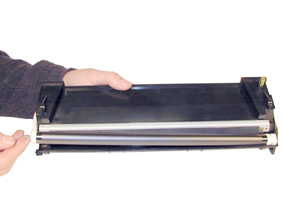
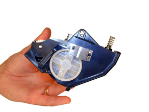
24) Install the toner supply section onto the waste chamber. Make
sure the spring on the supply hopper fits into the plastic ring
on the waste hopper. See Figures’ 30 & 31.
|
|
Figure
27 |
Figure 28 |
|
|
|
Figure 29 |
Figure 30 |
|
|
Figure 31
|
25) Install the two white plastic locking pins. Rotate them so
that they lock. Be careful not to rotate the pins to far, or force
them to turn. Forcing them will cause the small locking tabs to
break off. See Figure 32
26) Remove the two screws from the white pins. See Figure 33
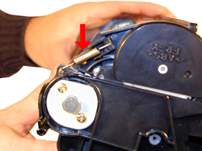
27) Install the spring onto the outside of the cartridge. See Figure
34
|
|
Figure
32 |
Figure 33 |
|
|
|
Figure 34
|
We have found no strange defects related to these cartridges. The
following is a list of repetitive defects for the more common failures.
94mm OPC Drum
36mm PCR
52mm Magnetic Roller
Press the MENU button until "UTILITIES MENU" is displayed.
Press SELECT
Press the MENU button until the test print desired is displayed.
Press SELECT
The test prints available are:
PCL FONT LIST
PS FONT LIST
MENU MAP
DEMO PAGE
The error codes in these machines follow the trend of using all
English messages (No Number Codes). The modules in the printer are
the "Smart Type”, where they can report a problem to
the main board. All messages are self-explanatory (failed fuser
says BAD FUSER). Paper jams indicate where the jam is located etc.
© 2003-2004 Summit Laser Products, Inc.
Any attempt to reproduce any part of these instructions without the written
consent of Summit Laser Products, Inc is prohibited. All registered trademarks
are the property of their respective owners.
|