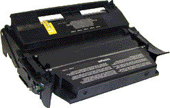
*Lexmark T620/622 Toner Cartridges
DOC-0304
Remanufacturing the Lexmark T620(4069-5XX,7XX) Series Toner cartridge
First introduced in June 2001, the Lexmark T620 series is based on the
Lexmark 4069-5XX,7XX 1200 dpi engine. Depending on the model, the print speed is
from 30-40 pages per minute. Although these machines are based on the older
Optra T 610 engine, (4069) these machines are faster. Due to the speed and fuser
characteristics, the toner is completely different. This toner is also different
from the T520 series.
Lexmark breaks down the engines as follows:
| T620 |
4069-520 |
| T620n |
4069-52N |
| T622 |
4069-722 |
| T622n |
4069-72N |
All take the same cartridges, but the printer parts can vary from machine to
machine.
Apparently to cut their costs, Lexmark is no longer using a drum cover on
their cartridges (See Diagram #1). Replacement drum covers should be available
soon.
These cartridges have ARD (Anti-Recycling devices) installed in the Prebate
cartridges that will not allow the cartridge to be used again until the chip
board is replaced. As with other Lexmark cartridges, the Non-prebate cartridges
will work with out replacing the chips. At the time of this writing, replacement
chips are available that are either single use, or multiple use. If you are not
going to get the cartridge back, use the cheaper, single use chip. If you are,
use the multiple use chip. The only thing to be aware of is that if (or when)
Lexmark changes the firmware in the machines, the multiple use chips will no
longer work. Lexmark has even set up flash updates on their web site for
existing customers to "upgrade" their machines, making even the
remanufactured cartridge that is in the machine un-useable!
The Encoder wheel in these cartridges does not control the toner yield as in
past cartridges, that is done by the chip. The encoder wheel only indicates if
the cartridge is a Prebate or not. See diagram # 2 for the two versions. The
Non-prebate wheel in our cartridges is made of white plastic, where the non-prebate
is black.

FIGURE 1 |

FIGURE 2 |
For cartridges used in MICR only machines, make sure that the chip you are
using will work. This is also strictly a chip function. If the cartridge is to
be used in other than a Lexmark machine the chip is different again. So far IBM
and Toshiba are using this engine. Again, check with your chip supplier to make
sure that their chip will work with your machine.
All that being said, these cartridges have a huge profit potential (See
below). Even with the extra cost of the chip, and having to be careful what
machine it goes into, they are more than worthwhile to do. The cartridge design
is based on the older Optra S. Out of all the Lexmark designed cartridges this
is by far my favorite. It’s easy to do with very few headaches.
The Lexmark Part #'s for these cartridges are as follows:
- Prebate 10K* cartridge: 12A6860 list $192.00**
- Prebate 30K* cartridge: 12A6865, List $471.00**
- Regular 30K* cartridge: 12A6765, List $521.00**
* Yield based on 5% coverage
** List prices current as of September 1st 2002
As with the Optra S machines, the PCR is not in the cartridge, it's
in the printer, and is rated for 300,000 pages. The Wiper Blade inside
the cartridge has an external felt brush that keeps the PCR clean. It should also be noted that because of the
play between the toner hopper and the
OPC drum, a shipping lock should be installed in every cartridge. This holds
true even if you are going to hand deliver thecartridge. Cartridge
/ machine troubleshooting as well as how to take test prints will be covered at
the end of this article.
- Toner approved vacuum.
- A small screwdriver (Common Style)
- A Phillips head screwdriver (#1)
- Needle-nose pliers
- Spring Hook
- 1 Bottle T620 870g toner for 20k cartridge, use 435g for 10K cartridge
- Drum padding powder (Kynar) Do NOT use Zinc Sterate on these cartridges!
- Cotton Swabs
- Isopropyl Alcohol
- Cotton Pads
- Long life OPC Drum (Optional)(4059 Style)
- Wiper Blade (4059 Style)
- Shipping Lock
- Aftermarket drum cover
- Felt Wand (4059 Style)
- Recovery Blade (4059 Style)
- Conductive Grease
- Vacuum the exterior of the toner cartridge.
- Place the cartridge on the bench drum side up (Label face down), and
the toner supply towards you.
- With the needle nose pliers or a spring hook, remove the two springs
from each end of the cartridge. See Diagram #4
- Note that there are two posts from the hopper that fit into the cartridge
shell. Pull the shell out to release the posts, and lift up
the hopper so that the posts are free. See Diagram #5

FIGURE 4 |

FIGURE 5 |
- Slide the hopper to the right, and remove from the cartridge. Pull it out
so that the large white bearing comes free. Place the hopper aside. See Diagram
#6
- Remove E-Ring from the small helical gear end of the drum axle.
There is no need to remove the other E-ring. See Diagram #7

FIGURE 6 |

FIGURE 7 |
- Slide the Drum Axle out of the cartridge. Hold the small helical gear
while pulling it out so that the drum is not damaged in the process. Note the
location of the spring. See Diagram #’s 8 & 9

FIGURE 8 |

FIGURE 9 |
- Gently lift the Drum and Drum washer up and out of the cartridge, and
place in a light protected area. Be careful not to lose the spring, it's purpose
is to keep the drum from rotating backwards. See Diagram #10
- Remove the Wiper Blade by removing the two screws from the Wiper Blade.
See Diagram #11

FIGURE 10 |

FIGURE 11 |
- Turn the cartridge so that the waste bin is face-up. Take a razor blade
and cut the foam seal that runs the back edge of the blade so that it is separated
from the cartridge. Make sure to cut along the plastic, and not the blade. See
Diagram #12
- Hold the cartridge so that it is up right (Standing up with the waste
bin on the table). With one hand, hold the laser shutter open, and
with the other hand, remove the Wiper Blade. See Diagram #13
NOTE1: The OEM Wiper Blade has the PCR cleaning assembly attached to it. It cannot be removed from the Blade
without damaging it. Our new
replacement Wiper Blades come complete with this assembly attached.
NOTE2: The "Starter cartridges" that came with a new printer do not have the PCR Cleaning Assembly on the
Wiper Blade.

FIGURE 12 |

FIGURE 13 |
- Make sure that the two end foams are clean and in their proper place See
Diagram #14
- Pad the new Wiper Blade with Kynar padding powder, replace the blade and two screws into the cartridge. See Diagram
#15

FIGURE 14 |

FIGURE 15 |
- Place a piece of tape along the edge of the Wiper Blade. If the tape
does not stick well, the area should be cleaned with alcohol. It
is very important to get a good seal with the tape, otherwise the cartridge
will leak. Trim away any excess tape. See Diagram #16
NOTE: Be careful not to allow any tape into the laser port opening!
- Remove the Recovery Blade entirely, and shake the toner out of the
debris cavity into the garbage can and vacuum clean. Removing the
Recovery Blade allows greater access to the waste toner. See Diagram #17

FIGURE 16 |

FIGURE 17 |
- Install a new recovery blade with a recovery blade insertion tool. Use of
this tool will keep the blade from becoming damaged. See Diagram #18
- With a small common screwdriver, gently pry off the Encoder Wheel.
Pry it off from the center shaft so that the wheel does not become damaged.
Place the wheel in a safe place. Remember, this wheel tells the
cartridge what type of cartridge it is, Prebate or Non-Prebate. The chip tells
the machine what type of yield the cartridge has. If this wheel becomes damaged,
it must be replaced with a wheel from another cartridge. See Diagram #19

FIGURE 18 |

FIGURE 19 |
- Remove the Doctor Blade Spring by pressing down on the center of
the spring. See Diagram #20
- On the left (fill Plug) side of the Static Roller there is a small metal
bushing, take a small screwdriver, and turn the bushing up so that the tab on the bushing is facing up. This will release
the bushing, and Static Roller. See
Diagram #21

FIGURE 20 |

FIGURE 21 |
- Remove the Static Roller, and bushing. See Diagram #22
NOTE: Always remove the Doctor Blade Spring before removing the
Static Roller, failure to do this will allow the Doctor Blade to
slide down from its original position.
- Remove the fill plug from the hopper. Pry the plug out from the base
next to the hopper. The fill plug is also a breather cap. It is best to remove
both sections at once and to clean them from the outside. These plugs tend to
leak if they have been separated. See Diagram #23

FIGURE 22 |

FIGURE 23 |
- Vacuum the Toner Hopper clean.
- With a cotton swab dipped in alcohol, clean the Static Roller seals
located on either end of the static roller section. These seals are
made of a white plastic. Also clean the electrical contact that touches
the Static Roller shaft. See Diagram #24
- Carefully vacuum or blow off the Static Roller, Be careful not to
touch the roller with your hands, or to damage this roller in any way.
- Inspect the inner and outer retaining blades (Black Mylar). If they are
bent in any way, they must be replaced as they will leak. See Diagram #25

FIGURE 24 |

FIGURE 25 |
- Install the white washers on the static roller, and on the NON-Keyed end of the Static Roller, install the bushing.
See Diagram #26
- Place the keyed end of the Static Roller into the cartridge, and
install the roller. Turn the bushing so that the tab is facing down.
This will lock the roller in place. See Diagram #27

FIGURE 26 |

FIGURE 27 |
- Install the Doctor Blade Spring. See Diagram #28
- Fill the hopper with the appropriate amount of toner. Remember, the
amount of toner that can be placed in the cartridge is controlled by
the chip. Use 600G for the 20k cartridge, and 250g for the
7.5k cartridge. Install the Fill Plug. See Diagram #29
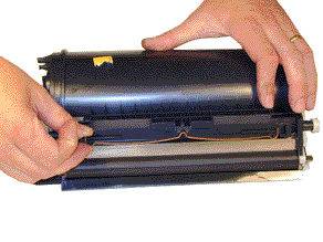
FIGURE 28 |

FIGURE 29 |
- Install the Encoder Wheel
- Remove the drum from the light protected area, and blow off any remaining
toner with the canned compressed air, and lightly coat with the
Drum Padding Powder,(Kynar). Do NOT use DPP (Zinc Sterate), this
powder will ruin the wiper blade.
- Place the OPC Drum into the cartridge with the small helical gear
on the NON-Contact side of the cartridge. Make sure that the spring is in the
proper position! See Diagram #30
- Install the Drum Axle pin into the small white gear side of the drum.
The Axle must be installed this way to prevent the axle from bending and
damaging the drum ground contact located inside the drum. See Diagram #31

FIGURE 30 |

FIGURE 31 |
- Install the E-Ring on the end of the axle. See Diagram #32
- remove the old chip with a pair of pliers, and install the new chip.
- Take the Toner Hopper and install it left side first. Make sure the
left side post, and the white bearing are in their proper slot. See Diagram #33
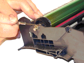
FIGURE 32 |

FIGURE 33 |
- On the right side of the cartridge, pull the cartridge shell out
so that the right side post falls into its slot. See Diagram #34
- With the spring hook, replace both springs on to the Toner Supply
Chamber. See Diagram #35
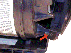
FIGURE 34 |
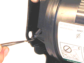
FIGURE 35 |
- Re-install the Static Roller drive gear. See Diagram #36
- A shipping lock must now be installed. This lock should be used even
if you are going to hand deliver the cartridge. It will prevent the
toner hopper from coming in contact with the OPC Drum, and causing damage
to either the Drum or the Static Roller. Press the two red tabs
into the sides of the cartridge as indicated in the picture supplied with
the lock.
When packaging the cartridge, make sure you include a new Felt Wand. Replace
the wand in the machine by lifting up the external plastic cover
located over the fuser assembly. Unlike most other printers, this
area cannot be reached from the inside of the machine!

FIGURE 36 |
Dirty Primary Charge roller Located inside the PRINTER, this will
show on the test page as vertical gray streaks down the page, or
as a gray background throughout the page.
Scratched drum this is shown by a very thin, perfectly straight line that runs from the top to the bottom of
the test page.
Chipped drum This will show as a dot or series of dots that repeat
2 times per page. Any drum defects will repeat 3 times per page
based on the drum circumference of 5.2".
Light damaged drum This will show up as a shaded area on the test
print that should be white. Again this will repeat 3 times per page.
Bad wiper blade This will show as either a gray line approximately 1/8" thick, or as shading across the
entire page. In either case there will
be a film of toner on the drum surface.
Weak Dr. Blade Spring This will
usually show as shaded areas on one or
both sides of the page.
| 31 |
Defective print cartridge We have no idea what
they mean by this. It is possible that the cartridge has too much
torque, and is loading down the gear train, but we just don’t know. |
| 32 |
Unsupported Print cartridge (Wrong chip,
encoder wheel combination, or bad chip). If this happens immediately
upon cartridge instillation, there is either a bad contact to the chip,
or the chip is bad. If the machine cycles and then the message appears,
the wrong encoder wheel is installed. |
| 80 |
Scheduled maintenance (300,000 page) |
| 88 |
Toner Low |
| 200-206 |
Various Paper Jams |
| 917 |
Bad transfer roller |
920
921
922
923
924
925 |
Fuser errors |
| 929 |
Toner sensor error This could be a bad developer drive
assy., bad cartridge, bad chip reader in the printer. Or the gear
opposite the encoder wheel shaft in the cartridge is out of place. Most
commonly this gear is the problem |
930
931-935 |
Print head (Laser unit) bad |
- Press the "MENU"(2) key until "Tests Menu" is displayed
- Press "SELECT"
- Press "MENU"(2) for a demo page
- Press "MENU"(2) to print the menus
- Press "MENU"(2) To print the fonts
- Press SELECT" again and the selected page will print
The Menu page also contains the printer page count, toner level, cartridge
serial number, cartridge size, if it is Prebate or not, and the cartridge
type, (Normal, MICR, Label).
There is also a series of test pages that can be run to help a technician
diagnose problems. To run these pages, do the following:
- Turn the printer off.
- Press and hold "Select" and "Return"
- Turn on the printer
- Release the buttons once "Performing self test" displays.
- Select "Print Quality Test Pages" from the menu.
- The printer will then print three pages:
Page 1 has the page count, printhead type (Laser unit), memory, processor
speed, machine serial number, cartridge information such as Toner level, cart.
Serial number, capacity, Prebate or Normal, margin settings, resolution,
density, fuser temp, print contrast and much more. There is a lot of
information on this page.
The next two pages have graphics only.
© 2003 Summit Laser Products, Inc. Any attempt to reproduce any part of
these instructions without the written consent of Summit Laser Products, Inc is
prohibited. All registered trademarks are the property of their respective
owners.

Contact Summit Laser Products
Toll Free Orders:
800-221-3516
Toll Free Fax: 888-791-9188
International Orders:
+1-631-218-8376
International Fax: +1-631-218-3285
Domestic Sales E-mail: sales@summitlaser.com
International Sales E-mail: export@summitlaser.com
Technical Support:
+1-631-218-8376
Technical Support E-Mail: tech@summitlaser.com
Mail: Summit
Laser Products
95 Orville Drive, Bohemia, New York 11716 - USA
Please report any broken links to:
webmaster@summitlaser.com
Authorized Summit Laser Distributors
All products on this web site, unless stated otherwise, are independently produced and distributed by Summit Laser, and not by the individual manufacturers of the copiers and printers referenced herein. Use of trade styles and trademarks of the individual manufacturers of the copiers and printers referenced herein are for descriptive purposes only and are not intended to imply any form of endorsement by the individual manufacturers of the refill or supply products offered herein. As such, all items in this catalog are deemed to be construed as “for use in,” “for use with or compatible with,” whether or not stated for each individual item as opposed to the group of items.
|


