

| Home |
New Arrivals!
|
Company Info
|
Publications
|
Special Features
| Contact Us |
 |
|
|
|
|
|
|

Samsung ML-1650 Toner Cartridges
DOC-0310
| Overview |
|
The Samsung ML-1650, ML-1651N , Tektronix Phaser 3400, and Tally T9216 series of printers are based on a Samsung 17 ppm, 1200 dpi engine. This engine is an updated version of the Samsung ML-6060. As with the ML-6060, these cartridges are at the same time deceptively easy and deceptively difficult to remanufacture. I will explain more as we go through the process.
The Samsung (ML-1650D8), Tektronix 3400 (106R00462) and Tally (043240) cartridges are rated for 8,000 pages at 5% coverage. Samsung and Tektronix also make the ML-1650D4, and 106R00461 cartridges respectively which are rated for 4,000 pages at 5%. Tally only has the high yield cartridge
The Samsung machines have some interesting features that come standard with the machine. They can print multiple pages on one sheet, and print posters by breaking up the image into parts that overlap each other. The amount of overlap can be controlled by the user. Both of these functions are accessed through the driver.
One important thing to watch out for is the toner save function. This is easily accidentally pressed as it has its own button on the control panel. If you are getting light print, check this out first.
A complete list of the machines based on the ML-1650 engine is as follows:
- Samsung ML-1650
- Samsung ML-1651N
- Tally T9216
- Tally T9216N
- Tektronix (Xerox) Phaser 3400
- Tektronix (Xerox) Phaser 3400B
- Tektronix (Xerox) Phaser 3400N
Figures’ A and B show the difference between the Samsung and Tektronix cartridges.
As the Tally machines are not sold in the US, I was not able to determine if the Tally and Samsung cartridges are interchangeable or not. More than likely, the notch on the front edge of the cartridge is in a different location.
These cartridges are not interchangeable with any of the many Samsung versions currently produced.
| Required Tools |
|
- Toner approved vacuum.
- A small Common screw driver
- #1 Phillips head screwdriver
- Needle nose pliers
- Spring Hook
| Required Supplies |
|
- 1651 toner, 240g (For 8k cartridge)
- Wiper Blade (Check for availability)
- OPC Drum (ML-6060)
- Sealing Strip (P8e)
- Developer Roller (P8e)
- Dr. Blade (Check for availability)
- PCR (Check for availability)
- Kynar padding powder
- PCR Cleaner
- Conductive grease
| Disassembly |
|
Clean the exterior of the cartridge.
Place the cartridge with the handle facing up. Remove the top 2 screws. See Figure 1
Tilt the hopper away from the screw holes and remove. To prevent the tabs from breaking, it is best to tilt it 180 degrees from the start position. Vacuum both the hopper but leave the cartridge base alone. There is a sensor that can be ruined if the base of the hopper is vacuumed. See Figure 2
CAUTION: The upper half of the toner hopper is being removed. If there is a lot of toner left in the hopper, it will dump out all over!
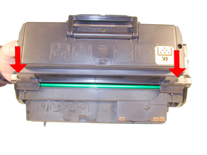 FIGURE 1 |
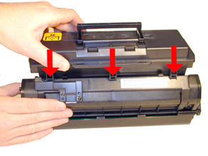 FIGURE 2 |
Remove the screw on the front toner low sensor contact plate. See Figure 3
Remove the two screws on the rear sensor plate. Remove the plate, sensor, and front contact plate. Note that the shorter screw is in the through hole, mounting directly to the sensor. See Figure 4
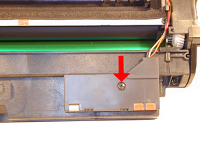 FIGURE 3 |
 FIGURE 4 |
Note the hole in the toner hopper where the toner low sensor was located. Vacuum any remaining toner from the base of the hopper. This should be done after the sensor is removed to prevent it from being destroyed by the static fields normally generated while removing toner.
Locate both the drum cover arms and gently pry them off. Try to keep the springs on the arms to make re-assembly easier later. Remove the entire cover assembly. See Figures 5 & 6
 FIGURE 5 |
 FIGURE 6 |
Remove the two screws on the Waste chamber. Lift the waste chamber off the cartridge. See Figure 7 & 8
 FIGURE 7 |
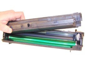 FIGURE 8 |
On the waste chamber, remove the two screws on the PCR clips. Remove the clips, and the PCR. Make sure you note the orientation of the PCR as each side is different. See Figure 9
Remove the two screws on the wiper blade. Remove the blade. Figure 10
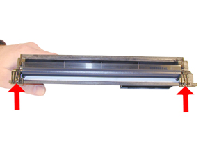 FIGURE 9 |
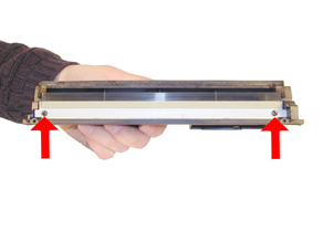 FIGURE 10 |
Clean out the Waste chamber.
NOTE: Be very careful not to damage or distort the thin Mylar Recovery Blade next to the wiper blade. If this blade is bent or damaged in any way, it should be replaced
Clean the PCR.
WARNING: Do not clean the OEM PCR with alcohol as this will remove the conductive coating on the roller. If the PCR is an after market, follow the cleaning methods recommended by the manufacturer. If the PCR is an OEM, we recommended it be cleaned with your standard PCR cleaner
Re install the Wiper Blade. New blades are at the time of this writing not available, but the OEM will easily last another cycle.
Reinstall the PCR and clips. Make sure that the long side of the PCR is to the left. Put the entire assy. aside. See Figure 11
Up to now this has been extremely easy. The next part on removing the drum had me going for a while. It’s not that hard, just very different. If you have ever done an ML-6060, it is exactly the same.
Remove the three screws on the left side end cap (small drum gear side). Remove the end cap. This end cap tends to have a very tight fit. Take your time and work it off. See Figure 12.
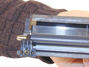 FIGURE 11 |
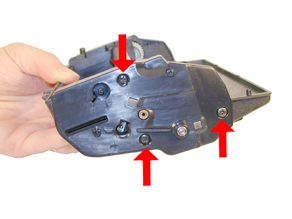 FIGURE 12 |
Remove the three screws indicated on the right side end cap. The fourth screw located in the raised lip (Colorized), is screwed into the drum axle, and uses a left hand thread. Make sure you turn that screw to the right to remove it. Keep this screw separate so it doesn’t get mixed up. It may be necessary to hold the opposite side of the drum shaft to keep it from spinning while removing the screw. See Figure 13.
NOTE: Although the drum axle pin looks like it should come out, it doesn’t. The drum axle has a slug/silencer attached to it inside the drum. To remove the drum, do the following:
Note the location of the gears and gear plate on the large gear side of the cartridge. Remove the Metal plate and gears. A drive belt will come loose as the plate is removed. This belt runs between the developer roller gear and the smaller of the two gears that stay on the gear plate. This belt presumably keeps the delivery of toner to the developer roller and from the developer roller to the drum smoother. A smooth turning developer roller will produce much more even gray scales. Make sure to note the orientation of the remaining gears as they are now loose. Remove the remaining gears. See Figures 14 & 15
From the large gear side, push the axle in as far as it will go. Lift up the large gear side, and press the axle back over from the small gear side, until the drum is released. See Figure 16.
We have removed the gear from an OEM drum to show the axle/silencer combo. New replacement drums come with the small drive gear installed, and the large gear just pressed in the drum, not glued. If the drum is being replaced, don’t forget to glue this gear in place! See Figure 17
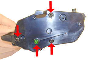 FIGURE 13 |
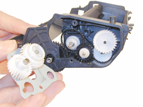 FIGURE 14 |
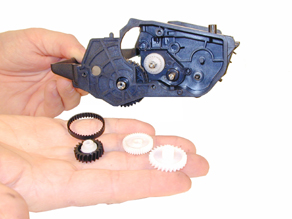 FIGURE 15 |
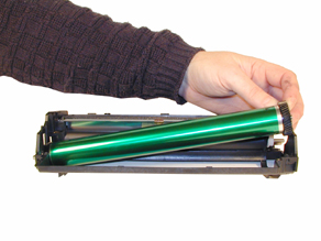 FIGURE 16 |
To clean the Dr. Blade (Highly recommended), the developer roller must be removed. These blades tend to get toner built up on them that can cause light streaks if not cleaned properly.
Locate the plastic plate the locks the developer roller in place. See Figure 18
 FIGURE 17 |
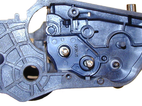 FIGURE 18 |
From the bottom of the cartridge, press in on the tab to release the plate. See Figure 19
Slide the plate forward so that the small tab at the top of the plate is free. Remove the plate. See Figure 20
 FIGURE 19 |
 FIGURE 20 |
Slide the developer roller out of the cartridge. See Figure 21
Clean the Dr. Blade. It can be removed to clean, but is not necessary. If you do remove it, be very careful not to tear the foam seals that attach to it. The P8e blade looks similar, but is just different enough not to fit correctly. See Figure 22
 FIGURE 21 |
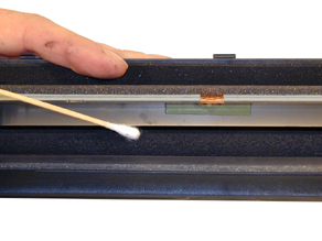 FIGURE 22 |
Clean the developer roller with a clean lint free cloth. Install back into the cartridge. Keep the longer shaft side to the gear side of the cartridge. See Figure 23
Re-install the locking plate over the developer roller shaft. Make sure that the top tab fits behind the frame. See Figure 24
 FIGURE 23 |
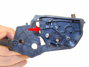 FIGURE 24 |
Install new drum axle and gears. Make sure you glue in the gears. The screw hole side of the axle is on the large gear side. See Figure 25
Re-install the loose gears, and belt onto the developer roller gear. As the metal plate with gears is inserted, slide the loose end of the belt over the front double gear. See Figures’ 26 & 27
Install the end cap and the four screws. Make sure that the machined left hand threaded screw is in the drum axle shaft. See Figure 28
 FIGURE 25 |
 FIGURE 26 |
 FIGURE 27 |
 FIGURE 28 |
Re-install the waste chamber and screws. Make sure that the end of the PCR shaft fits through the hole in the cartridge wall. See Figure 29.
Install the toner sensor, cover, and two screws on the base of the toner hopper. Make sure that the short screw is in the through hole, mounting directly to the sensor. See Figures’ 30 & 31
Route the wires as shown, install the contact plate and screw. Make sure that the front tabs lock in place. Figures’ 32, 33 & 34
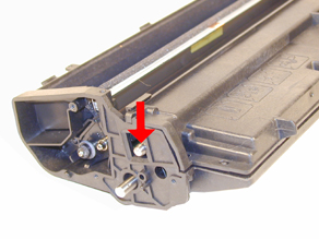 FIGURE 29 |
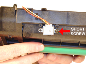 FIGURE 30 |
FIGURE 31
FIGURE 32
FIGURE 33
FIGURE 34
Install the seal on the toner hopper. See Figure 35
Remove the fill plug on the toner hopper and fill the hopper with the correct toner. Re-install the fill plug. This plug is made with a hard plastic, if it gets damaged; put a small bead of silicon around the lip to seal the cavity. See Figure 36


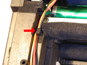
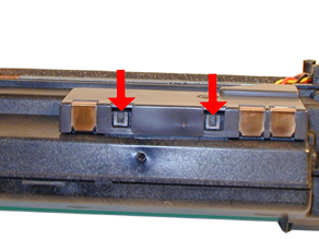
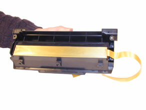 FIGURE 35 |
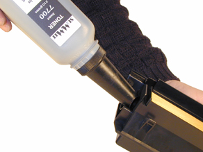 FIGURE 36 |
Slide the seal pull tab under the foam seal and out the cartridge wall. See Figure 37
Install the hopper back on to the cartridge. Start with the hopper upside down, slide the tabs in place, and rotate it until it is in place. Install the two screws. See Figures’ 38 & 39
Clean the contacts on the left end cap. Re-install the conductive grease. Install the end cap making sure the seal tab is inserted through the slot. See Figure 40
 FIGURE 37 |
 FIGURE 38 |
 FIGURE 39 |
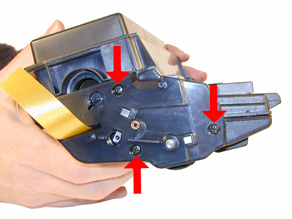 FIGURE 40 |
Install the drum cover. Press the spring tab into the slot in the end cap to set the spring tension. See Figure 41
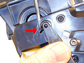 FIGURE 41 |
| Common Cartridge Problems |
|
Light print overall: Check to see if the toner save mode is on. (Button is easy to accidentally press as it is on the control panel.)
A Dirty or Bad Primary Charge Roller (PCR): located Inside the cartridge, this will show on the test print as vertical gray streaks down the page, as a gray background throughout the page, or as ghosting where part of a previously printed area is repeated.
Dirty PCR Connection: This will show as horizontal dark black bars across the page, or as shading throughout the page.
Scratched Drum: this is shown by a very thin, perfectly straight line that runs from the top to the bottom of the test page.
Chipped Drum: This will show as a dot or series of dots that repeat 3 times per page. Any drum defects will repeat 3 times per page.
Light Damaged Drum: This will show up as a shaded area on the test print that should be white. Again this will repeat 3 times per page.
Bad Wiper Blade: This will show as either a gray line approximately 1/8" thick or as shading across the entire page. In either case there will be a film of toner on the drum surface.
| Test Printing |
|
On the front panel of the printer there is a DEMO button. By pressing this button for different lengths of time, different pages will print.
Demo Page: Press and hold this button for about 2 seconds until the control panel lights blink SLOWLY. A demo page that has both text and graphics will print out
Configuration Page: Press and hold this button for about 6 seconds until the control panel lights blink RAPIDLY. A configuration page containing most of the printer’s settings will print out.
Printing a Cleaning Page:
Press and hold the DEMO button for about 10 seconds until the control panel lights STAY ON. The printer will run through a cleaning process, and print out a blank page. (This usually takes a while.) The process is done at this point; the printed page does not get run through again.
| Cleaning the Printer |
|
Not much of the machine is accessible. All that can be done easily is to vacuum the interior and wipe the lens down with a clean lint free cloth. The lens is located on the bottom of the top cover directly below the cartridge cover.
| Common Error Codes (Light Patterns) |
|
The error light patterns are not very helpful for anything besides a paper jam, but here they are:
Paper Jam: Paper LED is on, Error LED is on
Cover open/no cartridge: The error LED is on steady
Internal system error: All four LED’s blink in sequence, at a high rate of speed. See next error.
Engine error: Same as above, all four LED’s blink in sequence, at a high rate of speed. This can be caused by a memory crash, Main board or fuser error!
© 2003 Summit Laser Products, Inc. Any attempt to reproduce any part of these instructions without the written consent of Summit Laser Products, Inc is prohibited. All registered trademarks are the property of their respective owners.
![]()
Contact Summit Laser Products
Toll Free Orders: 800-221-3516
Toll Free Fax: 888-791-9188International Orders: +1-631-218-8376
International Fax: +1-631-218-3285Domestic Sales E-mail: sales@summitlaser.com
International Sales E-mail: export@summitlaser.comTechnical Support: +1-631-218-8376
Technical Support E-Mail: tech@summitlaser.comMail: Summit Laser Products
95 Orville Drive, Bohemia, New York 11716 - USAPlease report any broken links to: webmaster@summitlaser.com
Authorized Summit Laser Distributors
| Ukraine
Distributor SINT Company order@sint-master.com
|
All products on this web site, unless stated otherwise, are independently produced and distributed by Summit Laser, and not by the individual manufacturers of the copiers and printers referenced herein. Use of trade styles and trademarks of the individual manufacturers of the copiers and printers referenced herein are for descriptive purposes only and are not intended to imply any form of endorsement by the individual manufacturers of the refill or supply products offered herein. As such, all items in this catalog are deemed to be construed as “for use in,” “for use with or compatible with,” whether or not stated for each individual item as opposed to the group of items.