Remanufacturing the HP-1500/2500/2550 Black and Color Toner cartridges
0312
Unlike most basic engines, there have actually been three different releases to this series. The first in October 2002 was the HP-2500 series based on a 17 ppm (black) 600 Dpi engine, (2400 DPI with RET). Those machines went for approximately $1000.00 when new. Then in May 2003, the 1500 series were released. The 1500 series is based on a 16ppm, 600Dpi engine, but the new machine prices dropped to as low as $550.00! For both these groups, the color speed stayed at 4ppm, and the cartridges used are the same.
Then in June 2004, the 2550 series was released. The Black print speed jumped to 20ppm but the color still stayed at 4ppm. Resolution also stayed the same at 600Dpi (2400 Dpi with RET). The list price on these machines dropped to $499.00. The 2550 machines also use a new set of cartridges. Both groups of machines use a five cartridge system. Four color toners, and a separate drum cartridge. The cartridges used by these machine groups are as follows:
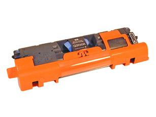
| Q3960A Black |
5,000 pages at 5% |
$115.54 List* |
| Q3961A Cyan |
4,000 pages at 5% |
$139.18 List* |
| Q3962A yellow |
4,000 pages at 5% |
>$139.18 List* |
| Q3963A Magenta |
4,000 pages at 5% |
$139.18 List* |
| Q3964A Drum |
20,000 Pages Black, 5,000 color |
$241.68 List* |
| Q3971A Cyan |
2,000 pages at 5% |
$103.00 List* |
| Q3972A Yellow |
2,000 pages at 5% |
$103.00 List* |
| Q3973A Magenta |
2,000 pages at 5% |
$103.00List* |
* The pricing on all cartridges is current as of April 2005. Prices at this time are the same for both series. According to HP, the actual average life expectancy for the drum unit is between 6000 to 8000 pages.
|
|
Figure 1 |
Figure 2 |
| 
|
|
Figure 3 |
Figure 4 |
| 
|

|
Figure 5 |
Figure 6 |
| 
|
|
Figure 7 |
Figure 8 |
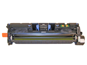
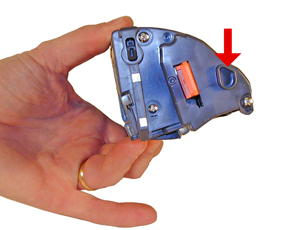
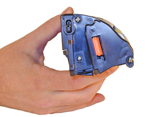
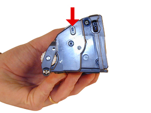
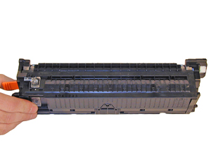
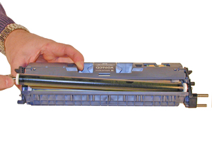
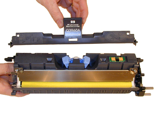
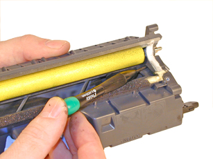
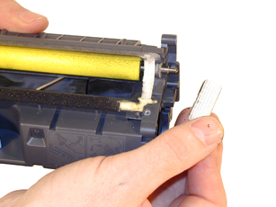
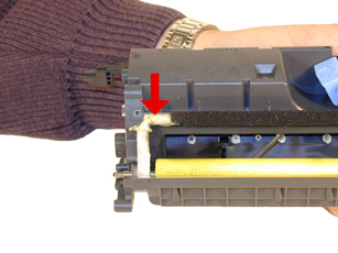
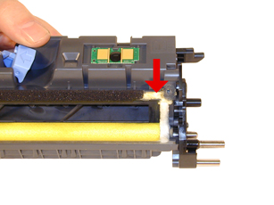
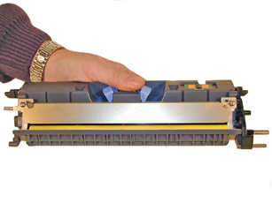
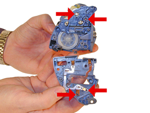
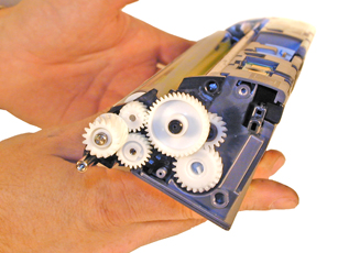
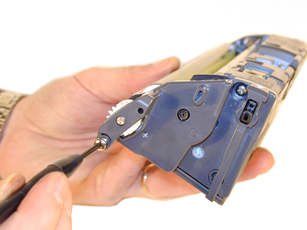
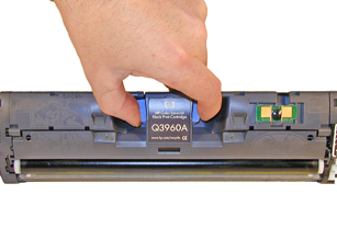
Figures 1-8 show the differences between the two cartridge types. Mainly the big differences are the two end caps. We are currently looking into universal end caps so that one cartridge can be used for both. The toner is the same for both cartridges. As with most other HP cartridges, these cartridges use a chip. Unlike previous HP color cartridges, the chip does not need to be changed in order for the cartridge to work. The toner low circuitry will be disabled, but after the user presses the CANCEL button, the cartridge will work.
The machines that use these cartridges are as follows:
HP-1500/2500 Engine
Canon imageClass MF8170C
Canon LBP-2410
HP Color LaserJet 1500
HP Color LaserJet 1500 L
HP Color LaserJet 2500
HP Color LaserJet 2500 L
HP Color LaserJet 2500 n
HP Color LaserJet 2500 Tn
HP-2550 Engine
Canon LBP-5200
HP Color LaserJet 2550 L
HP Color LaserJet 2550 Ln
HP Color LaserJet 2550 n
Unlike the HP-4600 engine which is a single pass engine, these machines are a carousel type. Similar to the HP-4500, but much more advanced. The carousel system is much less expensive to manufacture than the single pass systems. Probably one of the main reasons for this is that the single pass systems have a separate laser-scanner unit and all the associated circuitry for each color cartridge. The carousel system has one for all of them. Because of these differences, we will again go into the printer theory. While this system is not as complicated as a single pass, there is still quite a bit going on that has to happen in a very precise way. This is a bit a bit wordy, but if you are going to do these cartridges successfully, it is helpful to know how they work.
HP-2500 Color Printing Theory
|
|
Figure 9 |
Figure 10 |
| 
|
|
Figure 11 |
Figure 12 |
| 
|

|
Figure 13 |
Figure 14 |
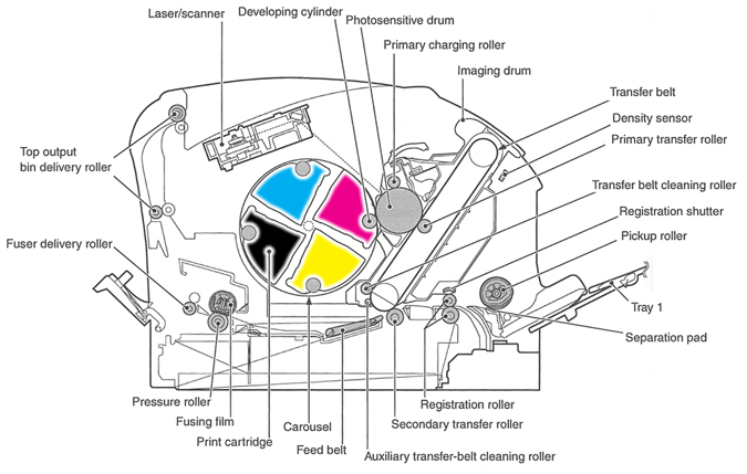
The HP-2500 color printing process is best explained as a series of stages. (Figure 9 shows a breakdown of most of the critical printer components as located in the machine.)
In the first stage, the Primary Charge Roller (PCR) places a uniform negative DC voltage on the OPC drum surface. The amount of the negative DC voltage placed on the drum is controlled by the printer’s intensity setting.
In the second stage, the laser beam is fired onto a rotating mirror (called the scanner). As the mirror rotates, the beam is reflected into a set of focusing lenses. The beam then strikes the drums surface, neutralizing the negative charge and leaving a latent electrostatic image on the drum. The areas where the laser did not strike the drum will retain the negative charge.
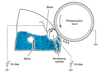
The third or developing stage (See Figure 10) is where the toner is developed on the drum by the developing section (or supply chamber), which contains the toner particles. As the toner stirring blade turns inside the hopper it pushes the toner towards the develop roller. The friction from this process causes a negative potential to develop on the toner. The toner will start to coat the developer roller. At the same time, a negative DC bias voltage is applied to the developer roller. This voltage is controlled by the printer’s intensity setting, and causes either more or less toner to be attracted by the developer roller. This in turn will either increase or decrease the print density. The final amount of toner on the developer roller is controlled by the doctor blade, which uses pressure and a second DC bias voltage to keep the amount of toner on the roller constant.
As the laser exposed areas of the OPC Drum approach the developer roller, the toner particles are attracted to the drum’s surface due to the opposite voltage potentials of the toner, and laser exposed areas of the OPC drum.
The fourth stage is the Primary transfer stage. This is where there are some large differences from monochrome printers and even the HP-4600,(See Figure 11). The first step in the Primary transfer stage is where the transfer roller places a positive charge on the back side of the transfer belt. The negatively charged toner on the drum is then transferred to the positively charged transfer belt. This process is repeated for each color. The positive DC bias voltage is increased for each successive color to make sure that all the toners stay in place on the belt.
The fifth stage is the secondary transfer stage. As the paper reaches the transfer belt, it also runs by the secondary transfer roller. This roller places a positive charge to the paper which causes the toner to transfer from the belt to the paper. After the transfer process is complete, another DC bias voltage is placed on the secondary transfer roller to prevent any toner from sticking to it.
The paper separates from the transfer belt with the help of the static charge eliminator and the stiffness of the paper.
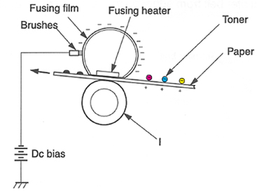
In the sixth stage, the image is then fused onto the paper by the fuser assembly. The fuser Assembly is comprised of the upper heating assembly and lower pressure roller. The lower pressure roller presses the page up into the upper heating assembly which then melts the toner into the paper. The upper heating assembly consists of a flexible sleeve with an induction type heating coil inside. This type of fuser affords “instant on” fusing with little to no wait time, and low power consumption. This sleeve also has a DC bias voltage on it to help hold the toner to the paper, and prevent it from scattering. See Figure 12
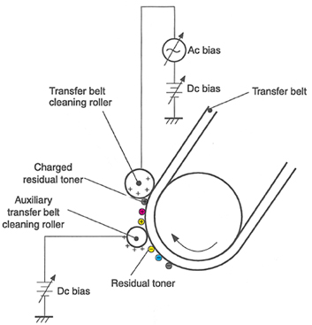
The seventh stage is where the transfer belt is cleaned. The transfer belt is cleaned whenever the printer is turned on, when the printer’s covers are closed, at the start of a print job, and after a specific number of pages. The auxiliary transfer belt cleaning roller has a positive DC bias voltage placed on it. This voltage actually keeps the toner on the transfer belt to prevent toner from falling off into the printer. See Figure 13
At this point another DC Bias voltage is placed on the transfer belt cleaning roller. These charges are stronger than the charge previously applied by the auxiliary transfer belt cleaning roller, so the earlier charge now behaves like a negative charge.
Is your head spinning yet?? It’s pretty straight forward from this point on…
Another DC bias voltage is placed on the transfer belt by the transfer roller to produce a difference between the belt and OPC drum. Another DC bias voltage is placed on the OPC drum cleaning roller. This causes the transfer of the residual toner to the drum.
The last stage is the drum cleaning stage. See Figure 14 The drum is cleaned after all the above takes place by the wiper blade. This part is fairly standard; the wiper blade scrapes the toner off the drum, and the recovery blade guides it into the waste chamber. The difference here is the movement of the waste toner to the waste toner case. The waste toner is picked up from the drum unit by an auger or waste toner screw as HP calls it. The toner moves across the waste toner transport plate to another auger which moves it finally to the waste toner case. This waste toner case is part of the transfer belt.
As you can see, the DC power supply (Dc Bias voltages) is extremely busy during the entire printing process. All though these machines have proved very reliable, I can see where even a small deviation from this power supply can cause major issues.
Printer Calibration:
At the start of all this is the calibration cycle. The printer will calibrate itself whenever the printer is turned on, when a new toner or drum cartridge is installed, and at specific page intervals determined by the total number of pages printed. Calibration consists of a solid block and halftone of each color being printed to the transfer belt. As the printed areas get to the top of the belt, a sensor will detect them, measure the density, and adjust the printer accordingly.
Toner Low:
Toner low is determined by sending a beam of light through the cartridge. There are two separate clear plastic lenses on the non-gear side of the cartridge. If the amount of light received at the optical receiving sensor is below a predetermined threshold, the toner low signal stays off. If the amount of light received is above that threshold, toner low comes on and is written to the chip.
Reset Chips:
These Reset chips (or “memory tags” as HP likes to call them), function the same as other HP chips. They control the “Toner Low”, “Toner out”, and “Replace (Color) Cartridge” Messages. Each color cartridge has a specific chip. Be careful not to mix them up. As stated earlier, the chips do not need to be replaced for the cartridge to function, but all the toner low functions will be disabled if they are not. When a used chip is used, the “CANCEL” button must be pressed to clear it. At this point a Non-HP Print cartridge will show. This message shows the first time only. The supplies status page will print, but no cartridge information will be listed. At the time of this writing, separate dedicated chips are in development, but we are also working on a universal chip that when combined with the universal end cap will allow you to build one cartridge for both engines.
Due to the nature of color toner, it is not recommended that the initial color of a cartridge be changed. It is virtually impossible to get all the toner out of a cartridge, and if two colors are mixed, the color output will be affected. Another reason not to try and interchange is that there are tabs in one location for black cartridges, and in another for color. These tabs are what the disengage block uses to move the developer roller away from the drum.
Taking test prints, cartridge troubleshooting as well as minor printer troubleshooting will be covered at the end of this article.
2500/2550 Dedicated Color Toner
-
New replacement chip (Separate chips for each color)
-
Shipping cover
-
Lint free Cloths
-
Conductive grease
-
Non-hardening silicon caulk (GE, Phenoseal brands work great)
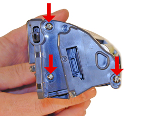
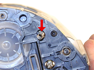
1) Remove the three screws from the right or non-gear side end cap. Note that the bottom screw is smaller than the others, and that the screw by the developer roller is longer. Use a jewelers or #0 Phillips head screwdriver to remove the bottom screw. Remove the end cap. See Figures 15 & 16
2) Remove the two screws from the gear side end cap. Note that the screw by the gear is a machine type. See Figure 17
| 
|
|
Figure 17 |
Figure 18 |
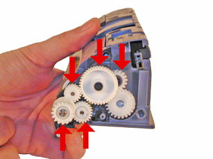
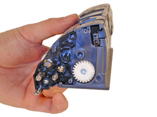
3) Note the gear locations, and remove the 5 indicated gears. Leave the large gear that drives the mixing blade in place. See Figures 18 & 19
| 
|

|
Figure 19 |
Figure 20 |
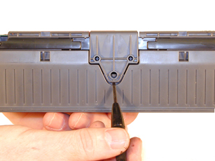
4) Remove the single screw from the stabilizing plate located on the non-gear side. Remove the plate. Be careful not to loose the spring attached to the doctor blade. See Figures 20 & 21
| 
|
|
Figure 21 |
Figure 22 |
5) Remove the developer roller. See Figure 22
6) Remove the fill plug, and dump out any remaining toner. Again, be careful not to loose the spring attached to the doctor blade. The spring can be removed, but sometimes it is very hard to put back on correctly. See Figure 23
| 
|
|
Figure 23 |
Figure 24 |
7) Remove the doctor blade cover by gently prying up from the center tab. Remove the cover by lifting it up. You may have to use a knife to separate the cover from the sealing foam. See Figures 24 & 25
| 
|

|
Figure 25 |
Figure 26 |
8) Remove the two screws and doctor blade. Carefully cut the sealing foam away from the bottom of the blade. If you are going to re-use the blade, be very careful not to bend it. See Figures 26 & 27
9) Vacuum/blow the cartridge clean.
| 
|
|
Figure 27 |
Figure 28 |
10) If you are going to install a seal, remove the seal exit plug by pushing it out from the inside, and then pulling it out from the outside. See Figures 28 & 29.
| 
|

|
Figure 29 |
Figure 30 |
11) Clean the developer roller and doctor blade seals. See Figure 30
12) Install the seal. See Figure 31
| 
|
|
Figure 31 |
Figure 32 |
13) Check the dr. blades sealing foam. This is the same type used in the HP-4200/4300 series. If it is still sticky, it can be re-used. If not, remove it with a razor knife, and replace it with a small amount of silicon caulk. See Figures 32, & 33
| 
|
|
Figure 33 |
Figure 34 |
14) Install the doctor blade and two screws. See Figure 34
| 
|

|
Figure 35 |
Figure 36 |
15) Fill the hopper with the correct toner for this cartridge. Remember, it is not a good idea to change the colors! Install the fill plug. See Figure 35
16) Install the developer roller. Large hub side to the gear side of the cartridge. See Figures 36
| 
|
|
Figure 37 |
Figure 38 |
17) Install the stabilizing plate and screw. Make sure the small bearing is not worn or damaged. See Figure 37
18) Clean the contacts on the inside of the end cap, and associated roller hubs. Replace with new conductive grease. See Figure 38
| 
|

|
Figure 39 |
Figure 40 |
19) Replace the end cap and three screws. Remember that the long screw is installed by the developer roller. See Figure 39
20) Install the doctor blade cover. Insert the pin into the hole in the end cap, drop the other side in place. See Figure 40
| 
|
|
Figure 41 |
Figure 42 |
21) Install the 5 gears as shown. See Figure 41
22) Install the end cap and two screws. Machine screw is installed by the developer roller. See Figure 42
| 
|
|
Figure 43 |
Figure 44 |
23) Replace the chip. See Figures 43
24) Make sure the lacking assembly is working properly. See Figure 44
| 
|
|
Figure 45 |
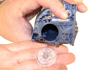
25) Install the plastic developer roller cover. See Figure 45
-
Toner approved vacuum or toner approved dust collector system
-
A small screw driver (Common Style)
-
A Phillips head screwdrivers #1, #0
-
Needle Nose Pliers
-
Small razor knife
-
Jewelers screwdriver set
Primary Charge Roller (PCR); The primary charge roller if dirty will show on the test print as vertical streaks down the page, or as a background throughout the page. If there is any physical damage, it will repeat at intervals of 38.1mm. If the back grounding is not all the same color, that usually indicates that more than one cartridge has a problem. Use a color chart to determine what cartridges are bad. (green = cyan and yellow) etc.
A Dirty PCR Connection will result in dark color horizontal bars across the page, or as shading throughout the page. Color will follow the color of the cartridge
A Scratched Drum will show up as a very thin, perfectly straight line that runs from the top to the bottom of the test page.
A Chipped Drum will result in a dot or series of dots that repeat at 148.3mm intervals
A Damaged Developer Roller will either leave a mark or a blank spot (depending on the type of damage) at intervals of 33.9mm.
A Light Damaged Drum will show up as a shaded area on the test print that should be white. Again this will repeat at intervals of 148.3mm.
A Bad Wiper Blade will result in vertical shaded lines down the page, or as shading across the entire page. In either case there will be a film of toner on the drum surface.
Some of the more common Printer Error Messages:
These machines do not have a text display, everything is indicated by lights.
Toner low: A color cartridge light is on steady
Toner out/cartridge missing: A color cartridge light is blinking
Drum life low: Drum cartridge light is on steady
Drum life out/missing: Drum cartridge light is blinking
Non HP cartridge installed: cartridge light is blinking, and the Attention light is on. Press “Cancel” to continue.
Attention light blinking: Top cover is open, paper is out, paper jam.
If the printer has the Attention, Ready, and GO lights on, that indicates a service error. Press and hold the GO and CANCEL JOB buttons to see the secondary message
Secondary messages:
Attention, ready, Go lights still on: Beam detect error
Ready light on: Scanner error
Ready and Go lights on: Fuser error
Attention light blinking: Fan motor error
Calibrate Now
If you are experiencing problems with color in OEM cartridges, The “Calibrate Now” feature can be run. This forces a calibration cycle to run. This procedure does not always fix the issue, but it can.
This must be done through the HP Color LaserJet 2500 series toolbar installed on the PC.
Open the Color LaserJet 2500 series toolbar
On the Troubleshooting tab, click Diagnostic Tools
Click calibrate now.
Demo Page
With the printer ready, press the “GO” button once.
The Demo page will print out
Configuration/Supplies Status pages
With the printer ready, press the “GO” and “CANCEL JOB” buttons simultaneously.
Both the Configuration, and the Supplies Status pages will print out
Repetitive Defect Chart:
| Pre ICL Roller |
22.1mm |
| Developer Roller |
33.9mm |
| ICL Roller |
37.9mm |
| Primary Charge Roller |
38.1mm |
| RS Roller |
41.9mm |
| T1 transfer Roller |
44.3mm |
| T2 transfer Roller |
56.9mm |
| Fuser Pressure Roller |
66.6mm |
| Fuser film |
75.6mm |
| Transfer belt drive roller |
89.0mm |
|
Transfer belt tension roller |
90.0mm |
| OPC Drum |
148.3mm |

|