

| Home |
New Arrivals!
|
Company Info
|
Publications
|
Special Features
| Contact Us |
 |
|
|
|
|
| |
HP-4200/4300 Toner Cartridges
DOC-0314

| Overview | |
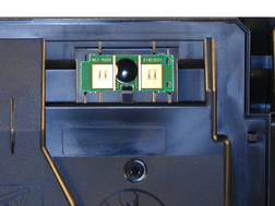
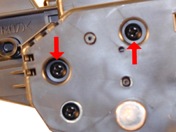
First introduced in November 2002, the HP LaserJet 4200 engine is a 35ppm, 1200 dpi engine, the HP LaserJet 4300 is a 45ppm, 1200 dpi engine, both made by Canon. The Q1338A cartridge (4200), is rated for 12,000 pages at 5%, the Q1339A (4300) cartridge is rated for 18,000 pages at 5%. As with the HP-4100 the chip is mainly controlling the toner low functions and of course the HP/Non HP cartridge message. These new chips are physically different in that they use physical contacts to “talk” to the printer (See Figure 1). The HP-4100 chips use RF (radio frequency) technology, where no physical contact is needed. These newer chips are also very noticeable, being placed on the top leading edge of the cartridge, and bright green in color. HP apparently is not making any effort to disguise the use of these chips. The chips themselves are held in place by double-sided tape.
FIGURE 1In our tests the OEM cartridges did not meet their stated yields. The 4200 cartridges yielded 11,060 pages (vs. 12,000), and the 4300 cartridges yielded 16,009 pages (vs. 18,000). The densities for both were on the dark side with the 4200 averaging 1.54, and the 4300 averaging 1.55. This higher than normal density probably accounts for the low yield.
These instructions cover both the 4200 and 4300 cartridges. Although they are not interchangeable, the procedure to remanufacture them is for the most part, identical. The only major exception is removing the wiper blade on the 4300 cartridge. The 4300 cartridge (39A) has a plastic shelf that must be removed in order to remove the wiper blade. The 4200 (38A) cartridge does not have this shelf. Steps 14 and 14A show the different cartridges.
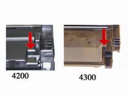
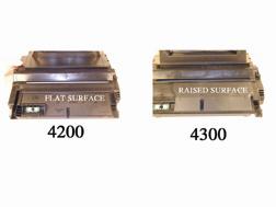
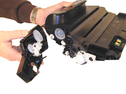
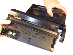
The first noticeable difference between the two cartridges is the height of the hopper, but there are many more subtle differences. The following Figures (2-5) show the difference between the two cartridges.
FIGURE 2
FIGURE 3
FIGURE 4
FIGURE 5As you can see, HP and Canon seem to have gone out of their way to design them so that they cannot be made interchangeable. I would have thought that having a low yield cartridge as well as a high yield cartridge would be the way to go, especially when you consider past history. Apparently the engineers at HP/Canon thought otherwise. The machines themselves also look very similar; they both have the same footprint, and what appear to be the same cases (except for the lids) See Figure 6
FIGURE 6
The toner used in both these cartridges is different from the 4100. It is not polymerized, but it is a Polyester based toner, and the melt point of the toner is approximately 10 degrees lower. For best results in these cartridges, we recommend that only Polyester based toners designed for these machines be used.
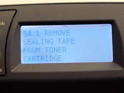
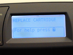
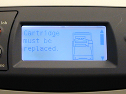
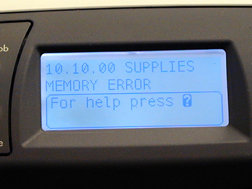
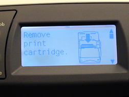
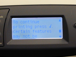
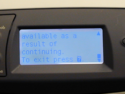
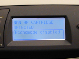
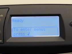
Figures 7-18 show the display panel when a cartridge is inserted into the machine in various states. Basically, it seems that the functions of this chip are the same as the 4100. The cartridge will work with out a chip, but the error message must be cleared first. At the time of writing this article (December 2002), it is not known if the toner low function will work if the chip is removed. We are still in the initial stages of testing these cartridges. By the time you read this, we should have this as well as other questions answered.
FIGURE 7New HP Cartridge
FIGURE 8New HP Cartridge, Seal left in
FIGURE 9HP Cartridge, Low Toner (This starts at about 2000 pages)
FIGURE 10Full cartridge, used chip
FIGURE 11Full cartridge, Used Chip (After pressing "?")
FIGURE 12Full cartridge, No chip (Screen 1)
FIGURE 13Full cartridge, No chip (Screen 2)
FIGURE 14Full cartridge, No chip (Screen 3)
FIGURE 15Full cartridge, No chip (Screen 4)
FIGURE 16Full cartridge, No chip (Screen 5)
FIGURE 17Full cartridge, No chip (Screen 6)
FIGURE 18Full cartridge, No chip (After pressing "Check" button)
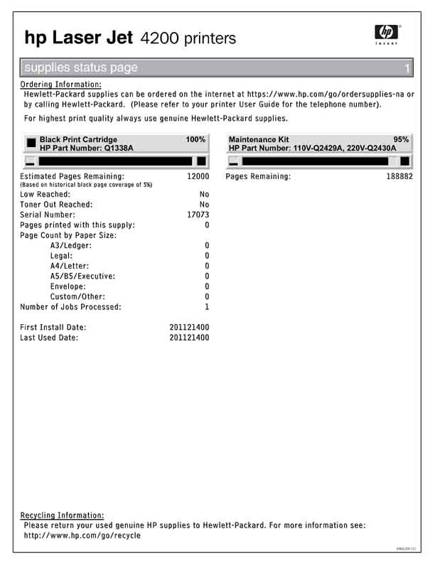
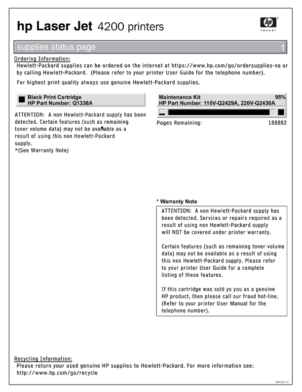
Figures 19-22 show the Supplies Status Page in the following states:
Note that as far as the supplies status page is concerned, an empty cartridge is the same as a full one with a used chip.
Printer usage, as well as some common printer/cartridge problems will be covered at the end of this article.


| Required Tools | |
- Toner approved vacuum.
- A small Common screwdriver
- A Phillips head screwdriver
- Needle Nose Pliers
- Dremel tool for removing Wiper Blade shelf on 4300 cartridges
| Materials Needed | |
- 690g Polyester based toner for 4200, 1100g for 4300
- Replacement drum
- Wiper Blade
- Doctor Blade
- PCR
- Magnetic roller sleeve
- Conductive Grease
- Tube of silicon for sealing wiper blade gap.
| Remanufacturing Instructions | |
- Place the cartridge with the toner hopper facing up and away from you. This will orient the cartridge for right and left sides.
- Remove the four screws on the left side end cap. See Figure 23
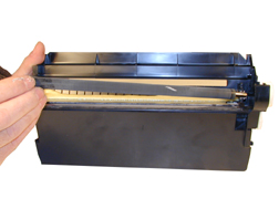
- Open the drum cover towards the back of the cartridge. Remove the left side metal bar. See Figure 24
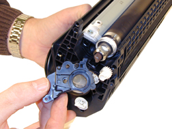
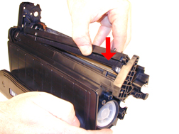
- Carefully pry off the drum cover plastic arm. The spring will probably pop off, take care not to loose it. We will go over the installation at the end of this article. See Figure 25
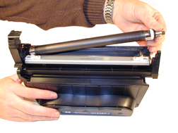
- Remove the metal bar from the right side, and remove the entire drum cover assembly. Make sure you put the spring in a safe place. See Figure 26
FIGURE 23
FIGURE 24
FIGURE 25
FIGURE 26
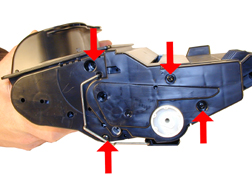
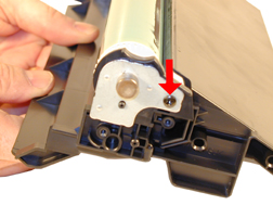
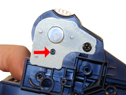
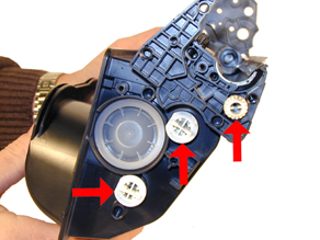
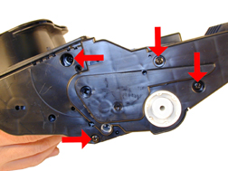
- Remove the two screws from the right side end cap. Do not remove the screw that is holding the recessed metal drum axle pin. See Figure 27
The rest of the right side end cap is held in place by three melted plastic posts. See Figure 28. Although there are tools to aid in removing this end cap, we have found it not necessary. After removing and replacing the waste chamber a few times, a technician will be much faster than going through the trouble to remove the end cap.
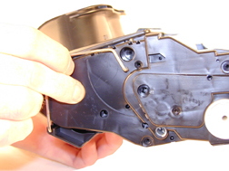
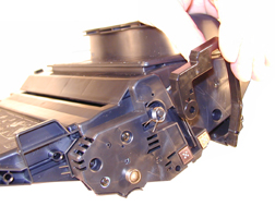
- Remove the left side end cap from the cartridge. See Figure 29
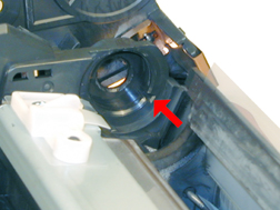
- Carefully work the waste chamber loose from the right side end cap. Press in on the metal drum axle pin to help free it. See Figure 30
FIGURE 27
FIGURE 28
FIGURE 29
FIGURE 30
- Remove the metal drum axle pin screw and the axle pin. See Figure 31
- Remove the drum. See Figure 32
- Remove the PCR. See Figure 33
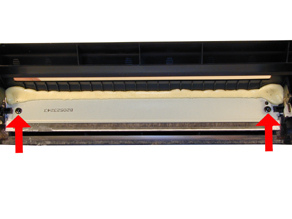
- Remove the two screws from the wiper blade. See Figure 34
FIGURE 31
FIGURE 32
FIGURE 33
FIGURE 34
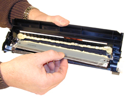
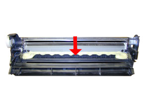
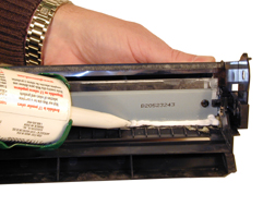
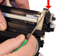
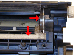
- With a razor knife, carefully lift up the seal foam and cut away. This is very sticky stuff, the best way to remove it is to cut and lift. The wiper blade can be resealed with a good quality silicon caulk. Make sure you use the type that never dries (Cannot be painted). See Figure 35
This foam seal is apparently a cheaper way to seal the cartridge instead of using a foam gasket. Although it is a real pain to remove, replacing it with silicon will allow you to easily peel it of the next cycle.
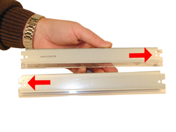
- Note the difference between the 4100 wiper blade and the 4200. At first glance they look very similar, but they are not. The tab behind the screw holes is a different size, and the alignment holes are on opposite sides. Due to the high speed and page counts of these cartridges, we recommend that they be replaced. It should be noted that the 4300 (39A) cartridge has a plastic shelf across the wiper blade that prevents it from being removed and replaced. This shelf is best removed by a Dremel type tool with a grinding bit, or a circular blade bit. We do not recommend that a knife be used as it is easy to slip and cut yourself See Figure’s 36 and 36A
- Clean the PCR with your standard PCR cleaner.
- Install the wiper blade and two screws. See Figure 37
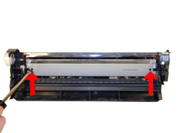
- Seal the back edge of the wiper blade with a good quality silicon caulk. Use the type that never dries. (Cannot be painted). Let the caulk dry for a few hours before doing anything else. See Figure 38
FIGURE 35
FIGURE 36
FIGURE 36a
FIGURE 37
FIGURE 38
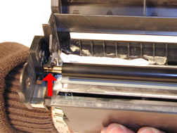
- Install the cleaned PCR. Place a small amount of conductive grease on the black PCR saddle. Remember, when using conductive grease, more is not better! See Figure 39
- Install the drum, drum axle pin and screws. Make sure that the plastic pin is centered in the oblong hole of the metal axle pin. (Just like the HP-4000 cartridges) See Figure 40
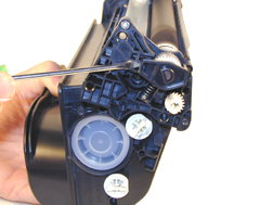
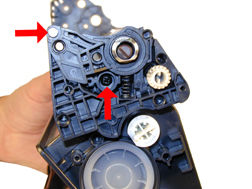
- Carefully pry up the Magnetic roller (MRS) cover, and remove. See Figure 41
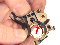
- Remove the small metal pin from the MRS holder. See Figure 42
FIGURE 39
FIGURE 40
FIGURE 41
FIGURE 42
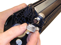
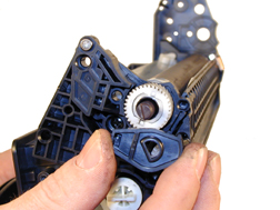
- Remove the MRS drive gear. See Figure 43
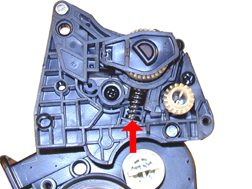
- Note the location of the spring that sits between the MRS holder and the hopper. Remove the screw, spring and the holder. See Figure’s 44 & 45
- Remove the MRS assembly. See Figure 46
FIGURE 43
FIGURE 44
FIGURE 45
FIGURE 46
- Remove the two Dr. Blade screws and the DR. Blade. Note the clear spacer that fits in between the blade and the white plastic spacer. Do not loose this spacer or light print will occur. See Figure’s 47 & 48
- Clean out all the remaining toner in the supply hopper.
- Note the magnetic seals on the MRS and the DB sealing foam. Make sure both are clean. See Figure 49
- Note also the new style magnetic roller contact. There are two copper fingers that fit top and bottom on the Magnetic roller. This when combined with the new larger diameter of the roller, allow the cartridge to run at the higher speeds that both machines are capable of. See Figure 50
FIGURE 47
FIGURE 48
FIGURE 49
FIGURE 50
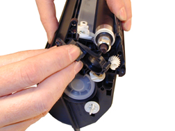
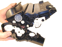
- There are three separate mixing blades in the toner hopper. The largest is on the bottom, with the smallest on the top. Each is driven by its own separate drive gear. See Figure 51
- The entire upper half of the toner hopper is different in that is “Floats” on a series of foam seals. The upper half can be removed from the hopper, but some of the seals will be destroyed. This may become necessary in order to seal the cartridge, we will keep you informed as our testing continues. See Figure 52
- Fill with 690g of 4200 Polyester based toner, 1100g for the 4300. See Figure 53
- Install the doctor blade and two screws (Make sure that all the spacers both clear and white are seated correctly!). See Figure 54
FIGURE 51
FIGURE 52
FIGURE 53
FIGURE 54
- On the MRS there is a small hub that is keyed into the MRS holder. Align the hub with its slot and install the hub as well as the entire MRS assembly. See Figure’s 55 & 56
- The opposite side holder is also keyed. Align the remaining hub and install into the holder. See Figure 57
FIGURE 55
FIGURE 56
FIGURE 57
- Install the holder and spring. See Figure’s 58 & 59
- Install the screw and the small metal pin. See Figure 60
- Install the MRS drive gear. See Figure 61
FIGURE 58
FIGURE 59
FIGURE 60
FIGURE 61
- Install the keyed MRS cover. Make sure that the keyed hole in the cover matches the keyed end of the magnet in the MRS assembly. See Figure 62
- Install the waste section into the fixed end cap on the supply hopper. This is a tricky process the first few times, but gets much easier. The best way to do it is to carefully pull the end cap out, and slide the waste up and in, until everything aligns. For the first few times, this is definitely easier said than done, but you will get the hang of it. See Figure 63
- Install the two screws into the end cap. See Figure 64
- Install the left side end cap. See Figure 65
FIGURE 62
FIGURE 63
FIGURE 64
FIGURE 65
- Install the four screws. See Figure 66
- Install the metal bars from the drum cover on both sides of the cartridge. You will have to turn the bars so that the flattened end of the bars fit into the keyed slots. See Figure 67
- Install the spring into the drum cover arm as shown. Pull the upper tail of the spring until it fits into the notch in the arm hub. See Figure 68
- Install the arm onto the cartridge. Release the spring from the notch so that the tail fits as shown. See Figure 69
- Replace the chip on the top of the cartridge. Replacing this chip will enable the toner low functions of both the cartridge, and the machine again.
FIGURE 66
FIGURE 67
FIGURE 68
FIGURE 69


| Common Cartridge Problems | |
Repetitive defect chart:
OPC Drum: 95mm
Magnetic Roller Sleeve: 63mm
PCR: 36mmDirty or Bad Primary Charge Roller (PCR); A bad PCR will normally cause a gray background, or ghosting. Small defects from the PCR will repeat every 36mm.
Dirty PCR Connection; This will show as horizontal dark black bars across the page, or as shading throughout the page.
Scratched Drum; This is shown by a very thin, perfectly straight line that runs from the top to the bottom of the test page.
Chipped Drum; This will show as a dot or series of dots that repeat 3 times per page or every 95mm. Any drum defects will repeat 3 times per page (95mm).
Light Damaged Drum; This will show up as a shaded area on the test print that should be white. Again this will repeat 3 times per page.
Tire Tracks; This is normally caused by a bad drum, they normally show up on the right edge of the page.
Damaged Magnetic Roller Sleeve; A damaged Magnetic Roller Sleeve will leave a mark that repeats every 63mm.
| Running the Cleaning Page | |
Press the “SELECT” Button
Press the “DOWN ARROW” until CONFIGURE DEVICE appears
Press the “SELECT” Button
Press the “DOWN ARROW” until PRINT QUALITY appears
Press the “SELECT” Button
Press the “DOWN ARROW” until CREATE CLEANING PAGE appears
Press the “SELECT” Button
Follow the instructions on the cleaning page to complete.
| Running Test Pages | |
Press the “SELECT” Button
Press the “DOWN ARROW” until INFORMATION appears
Press the “SELECT” Button
Press the “DOWN ARROW” until either:
MENU MAP,
CONFIGURATION PAGE,
SUPPLIES STATUS PAGE, or
PS or PCL FONT LIST appears
Choose the page(s) desired, and
Press the “SELECT” Button
| Printer Error Codes | |
These codes will be listed as soon as HP releases the service manuals for these machines.
© 2003 Summit Laser Products, Inc. Any attempt to reproduce any part of these instructions without the written consent of Summit Laser Products, Inc is prohibited. All registered trademarks are the property of their respective owners.
![]()
Contact Summit Laser Products
Toll Free Orders: 800-221-3516
Toll Free Fax: 888-791-9188International Orders: +1-631-218-8376
International Fax: +1-631-218-3285Domestic Sales E-mail: sales@summitlaser.com
International Sales E-mail: export@summitlaser.comTechnical Support: +1-631-218-8376
Technical Support E-Mail: tech@summitlaser.comMail: Summit Laser Products
95 Orville Drive, Bohemia, New York 11716 - USAPlease report any broken links to: webmaster@summitlaser.com
Authorized Summit Laser Distributors
| Ukraine
Distributor SINT Company order@sint-master.com
|
All products on this web site, unless stated otherwise, are independently produced and distributed by Summit Laser, and not by the individual manufacturers of the copiers and printers referenced herein. Use of trade styles and trademarks of the individual manufacturers of the copiers and printers referenced herein are for descriptive purposes only and are not intended to imply any form of endorsement by the individual manufacturers of the refill or supply products offered herein. As such, all items in this catalog are deemed to be construed as “for use in,” “for use with or compatible with,” whether or not stated for each individual item as opposed to the group of items.