

| Home |
New Arrivals!
|
Company Info
|
Publications
|
Special Features
| Contact Us |
 |
|
|
|
|
|
|
|
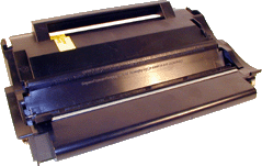
Lexmark T-420 Toner Cartridges
DOC-0318
| Overview |
|
The T420 series of printers use cartridges that look very similar to the Optra M, basically they are a modernized version of it. These cartridges use an ARD (Anti-Recycling Device). They also have an encoder wheel that I think is different. I can’t say for sure because I was not able to obtain a new NON-Prebate cartridge from any of my suppliers. (Gee what a surprise!) There are four different cartridges for these machines. Two high yield, two low yield. Prebate and Non-Prebate are available for both.
First released in February 2003, the T420 series are based on a Lexmark 22ppm, 1200dpi engine. So far only two models have been released, the T420d, and the T420dn. Both come standard with duplex capabilities and a fast 200 MHz processor that gets the first page out in less than 10 seconds.
As stated above, there are actually four cartridges currently available for these machines. They are as follows:
List prices are from Lexmark Web Site 3/1/03
Part# Type List$ Yield 12A7415 High yield Prebate $193.00 10,000 12A7410 Standard Prebate $99.00 5,000 12A7315 High Yield NON-Prebate $222.00 10,000 12A7310 Standard NON-Prebate $128.00 5,000 As with all the newer Lexmark cartridges, the PCR is not in the cartridge, it's in the printer. The wiper blade inside the cartridges I have seen do not use a PCR cleaner to keep the PCR clean as the OEM Optra M and aftermarket wiper blades do. The aftermarket Optra M wiper blades do fit though, the PCR cleaner doesn’t cause any problems. The first Optra M cartridges did not have a PCR cleaner on their wiper blades either, so they may show up on these as time goes by.
Because these cartridges use ARD chips, only the Non-Prebate cartridges can be remanufactured until new or repair chips are released. Unfortunately, along with our Non-Prebate cartridge, the printer was also back ordered. So as of now, I have no information on how the chip operates, or affects a remanufactured cartridge. Information will follow on this as soon as the printer arrives, and we can run our tests.
It should also be noted that because of the play between the toner hopper and the OPC drum, a shipping lock should be installed in every cartridge. This holds true even if you are going to hand deliver the cartridge. The shipping lock for the T420 is unique to these cartridges. Unlike the Optra M, these machines do not use felt wands to keep the fuser clean.
Taking test prints, as well as some common cartridge/machine problems will be covered at the end of this article.
| Required Tools |
|
- Toner approved vacuum.
- Small screw driver (Common Style)
- Phillips head screwdriver (#1)
- Spring hook
| Materials Needed |
|
- T420 black toner. Use 175G for standard yield cartridges, and 350g for high yield cartridges.
- Long life OPC Drum (Optional, specific to T420 cartridges)
- Wiper Blade (Optra M type)
- Shipping Lock (T420 only)
- New White Developer Roller Shims
- Drum padding powder (Kynar) or Sure-Lube. Do NOT use Zinc Sterate on these cartridges!
- Cotton Swabs
- Isopropyl Alcohol
- Poly Wipes Cotton Pads
| Disassembly |
|
Vacuum the exterior of the toner cartridge.
Place the cartridge on the bench drum side down, and the toner supply towards you.
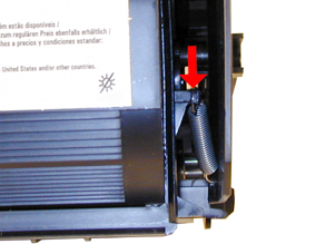
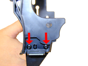
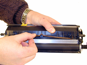
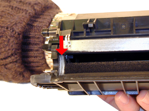
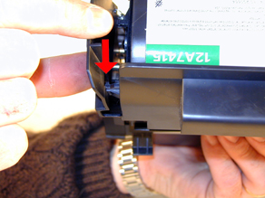
With the spring hook, remove the two springs from each end of the cartridge. The right side is easy to see, the left is somewhat recessed. See Figures 1 & 2
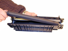
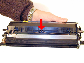
Lift up the 2 tabs on top of the cartridge to release the hopper. See Figure 3.
Remove the E-Ring from the small helical (white) gear end of the drum axle. There is no need to remove the other E-ring. See Figure 4
FIGURE 1
FIGURE 2
FIGURE 3
FIGURE 4
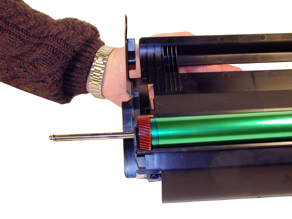
Slide the Drum Axle out of the cartridge. See Figure 5
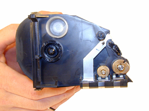
Gently lift the Drum and Drum spring up and out of the cartridge, and place in a light protected area. Be careful not to lose the spring from the large gear. Its purpose is to keep the drum from rotating backwards.
Cleaning out the waste chamber can be done two ways. The easiest way is to remove the drum cover, and then the two screws, and blade. The second way is also easy, it just is somewhat more time consuming. This method entails removing four screws, two from each side of the cartridge, and then the blade and two screws. The first method is covered in steps 8-9; the second is covered in steps 10-11
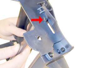
FIRST METHOD: To remove the drum cover, Bend the cover out in the middle of the cover so that the two side pins are released. See Figure 6.
Once the two small pins are released, slide the large tab on the cover out through the large hole in the side wall of the cartridge. See Figure 7
Proceed to step 12
FIGURE 5
FIGURE 6
FIGURE 7
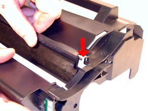
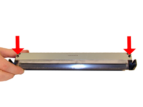
SECOND METHOD: Remove the two screws on each side of the waste chamber. (Four screws total). See Figures 8 & 9.
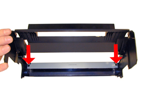
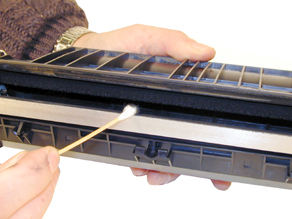
Remove the waste chamber from the cartridge. See Figure 10.
Remove the two screws and the wiper blade, from the waste chamber. Vacuum it clean. See Figure 11
FIGURE 8
FIGURE 9
FIGURE 10
FIGURE 11
Make sure the foam seal on the bottom of the wiper blade is not torn or the cartridge will leak. If you are using an Optra M aftermarket blade, place two strips of foam on the bottom of the blade. (Split hopper foam strips work great) See Figure #12
Pad the Wiper Blade with Kynar padding powder or Sure-Lube, replace the blade and two screws into the cartridge. See Figure 13
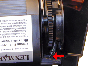
On the toner hopper, remove the Doctor Blade Spring by pressing down on the center of the spring. See Figure 14
FIGURE 12
FIGURE 13
FIGURE 14
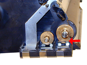
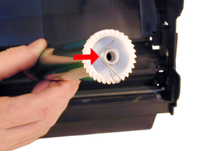
On the left side of the Developer Roller there is a small metal bushing, take a small screwdriver, press the contact plate down and pry the bushing off the shaft. See Figures 15 & 16
Remove the star gear from the developer roller, remove the developer roller. See Figure 17
NOTE: Always remove the Doctor Blade Spring before removing the Developer Roller, failure to do this will allow the Doctor Blade to slide down from its original position.
Remove the fill plug from the hopper. Pry the plug out from the base next to the hopper. See Figure 18
FIGURE 15
FIGURE 16
FIGURE 17
FIGURE 18
Vacuum the Toner Hopper clean.
With a cotton swab dipped in alcohol, clean the Developer Roller seals located on either end of the developer roller section. These seals are made of a white plastic. This also a good time to clean the bottom edge of the Dr. Blade. See Figures 19 & 20
Carefully vacuum or blow off the Developer Roller, Be careful not to touch the roller with your hands, or to damage this roller in any way.
If the OEM developer roller spacers are damaged, they should be replaced. The shims used on all previous Lexmark cartridges will work here also. Damaged shims will allow toner to leak out of the cartridge. See Figure 21
FIGURE 19
FIGURE 20
FIGURE 21
Place the keyed end of the Developer Roller into the cartridge, and install the roller. Install the metal bushing. Turn the bushing so that the oblong side locks into the cover plate. Install the star gear. See Figures 22, 23 & 24.
Install the Doctor Blade Spring. See Figure 25
FIGURE 22
FIGURE 23
FIGURE 24
FIGURE 25
Fill the hopper with the appropriate amount of toner. Install the Fill Plug. See Figure 26
If it was removed, install the drum cover. Install the large tab through the hole, and bend the cover in the middle so that the pins on both sides fit into their respective holes. See Figures 27 & 28.
FIGURE 26
FIGURE 27
FIGURE 28
Lightly coat the drum with Drum Padding Powder,(Kynar). Do NOT use Zinc Sterate.
With the cartridge upside down and the waste chamber facing you, place the OPC Drum into the cartridge with the white gear side of the drum to the right side of the cartridge. Make sure that the spring is facing down, and is in between the two slots. (The slots are only on the right side). See Figure’s 29 & 30.
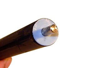
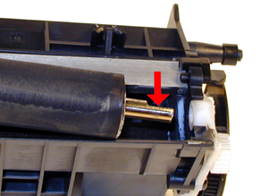
Install the Drum Axle pin into the large gear side of the drum. This is the opposite side from where the axle was removed. The Axle must be installed this way to prevent the axle from bending and damaging the drum ground contact located inside the drum. See Figure 31
Install the E-Ring on the end of the axle. See Figure 32
FIGURE 29
FIGURE 30
FIGURE 31
FIGURE 32
Spin the drum for a few revolutions towards the waste chamber to ensure the drum and wiper blade are properly lubricated.
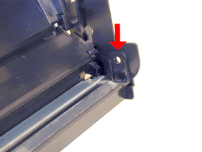
Install both springs into their respective holes in the cartridge side walls. See Figure 33
Take the Toner Hopper and install it straight in. Bend out the side wall of the cartridge so that the top pins are able to lock in place. See Figures 34 & 35
FIGURE 33
FIGURE 34
FIGURE 35
With spring hook, replace both springs on to the Toner Supply Chamber. See Figures 36 & 37
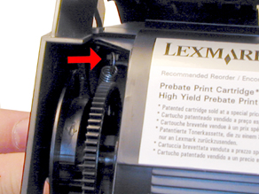
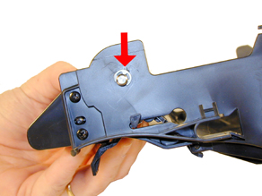
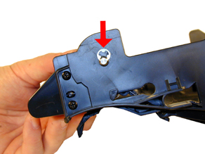
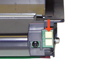
If this is a Prebate cartridge, the chip must be replaced. Remove the screw, and remove the old chip. Install the new chip, and replace the screw. See Figure 38
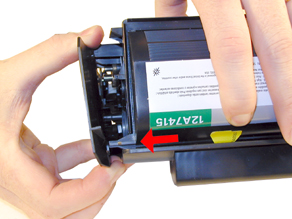
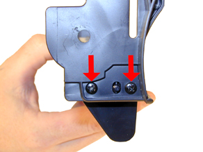
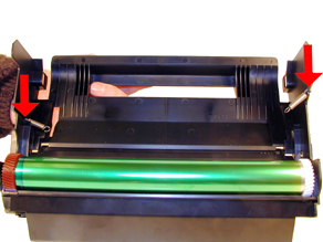
A shipping lock must now be installed. This lock should be used even if you are going to hand deliver the cartridge. It will prevent the toner hopper from coming in contact with the OPC Drum, and causing damage to either the Drum or the Developer Roller. Press the two red tabs into the sides of the cartridge as indicated. See Figure 39
FIGURE 36
FIGURE 37
FIGURE 38
FIGURE 39


| Common Printer Problems |
|
Print Head Lens: The print head lens should be cleaned periodically or when ever light print occurs. To clean it open the upper and lower doors, remove the cartridge. The lens is located across the frame just above where the cartridge sits. Clean the lens with a clean dry lint free cloth. Do not use any type of chemicals on the lens.
Transfer Charge Roller In the base of the printer, there is the Transfer Charge Roller. This is a foam roller that must be kept clean. Be very careful not to touch this roller with any part of your skin. The oils naturally present in your skin, and/or paper dust and toner dust will contaminate the roller causing light print and/or small white voids in the text. This should only be cleaned with a toner approved vacuum.
Dirty Primary Charge roller Located inside the PRINTER, this will show on the test page as vertical gray or black streaks down the page. These rollers can be cleaned with a high quality rubber roller cleaner. Try and use one that leaves no residue. Let it dry until the surface is no longer tacky.
| Light Sequences for Printer Errors |
|
Toner Low Flashing, Error Light ON; This can mean No cartridge, defective cartridge, or unsupported cartridge (bad chip)
Toner Low Flashing, Error Light Flashing; Invalid refill cartridge. (Chip not replaced on a Prebate cartridge
Error light on; Upper front door open.
Toner Low On, Paper Jam On, Press Continue On; Paper jam in between the input area and the exit area.
Load/Remove Paper On, paper Jam on, Press Continue On; paper Jam in the exit area
| Common Toner Cartridge Problems |
|
Scratched drum this is shown by a very thin, perfectly straight line that runs from the top to the bottom of the test page.
Chipped drum This will show as a dot or series of dots that repeat 3 times per page.
Light damaged drum This will show up as a shaded area on the test print that should be white. Again this will repeat 3 times per page.
Bad wiper blade This will show as either a gray line approximately 1/8" thick, or as shading across the entire page. In either case there will be a film
of toner on the drum surface.
Weak Dr. Blade Spring This will usually show as shaded areas on one or both sides of the page.
| Changing the Printer Density |
|
The density can only be changed through the printer menu in the software driver. This can not be done through the control panel on the printer.
| Running Test Pages |
|
Menu Settings Page:
Make sure that the ready light is on.
Press and release the “CONTINUE” button.
The menu settings page will print. If the machine is the network version, an addition network settings page will also printPrint Quality Test Pages:
Turn the printer off, and open the upper front door
Press and hold the CONTINUE button, turn the printer on. All the lights will cycle.
Release the CONTINUE button.
Close the Upper Door. The top four lights will be on, and a printer settings configuration sheet prints. Save this page!NOTE: If the ERROR light is on, the upper door is still open
Press and release the CANCEL button until the light sequence matches the sequence listed for Print Quality Test Pages on the printer setting configuration page previously printer.
Could they have made this more complicated?
Press and hold the CONTINUE button until all the lights cycle.
Release the CONTINUE button. Three pages will print, two graphics pages, and an information page.
| Cartridge Printing Theory |
|
There have recently been quite a few questions on the sequence of events in the print process, so we are including it here again. The process listed here is basically the same for all Non-Magnetic toner type cartridges
The first stage in the printing process is the conditioning stage. The Primary Charge Roller places a uniform negative DC voltage on the OPC drum surface. The amount of the negative DC voltage placed on the drum is controlled by the printer’s intensity setting.
In the second stage (also called the imaging section), the laser beam is fired onto the OPC drum surface. The laser beam dissipates the OPC drum charge to ground wherever it strikes the drum, leaving a latent electrostatic image. The OPC drum makes approximately three revolutions for each printed page.
The third or developing stage is where the toner is developed on the drum by the developing section (or supply chamber), which contains the toner particles. The toner is held to the developer roller by a DC voltage supplied by the high voltage power supply. This voltage is controlled by the printer’s intensity setting, and causes either more or less toner to be attracted by the developer roller. This in turn will either increase or decrease the print density. The toner is first fed to the developer roller by the feed mechanism. The amount of toner on the developer roller is controlled by the metal doctor blade, which uses pressure to keep the amount of toner on the developer roller constant.
As the laser exposed areas of the OPC Drum approach the developer roller, the toner particles are attracted to the drum’s surface due to the opposite voltage potentials of the toner, and laser exposed areas of the OPC drum.
This image is then transferred to the paper as it passes below the drum by the transfer charge roller, which places a positive charge on the back of the paper. This positive charge causes the negatively charged toner on the drum’s surface to be attracted to the page. The small diameter of the drum, combined with the stiffness of the paper causes the paper to peel away from the drum. The static charge eliminator weakens the attractive forces between the negatively charged drum surface, and the positively charged paper. Without this help, thin paper may wrap itself around the drum.
The image is then fused on to the paper by the fuser assembly, which is comprised of the upper and lower fuser rollers. The lower rubber roller presses the page up into the upper roller which then melts the toner into the paper.
The fourth stage is where the OPC drum is cleaned. On average, approximately 90% of the toner is transferred to the paper during the print cycle. The remaining 10% remains on the OPC drum and is cleaned off the Drum by the wiper blade, guided into the waste chamber by the recovery blade, and stored in the waste chamber.
The final stage is completed by the primary charge roller. This roller now places an AC signal across the OPC drum surface, which will erase any residual charges left on the OPC drum surface. The OPC drum is now ready to be conditioned by the PCR’s DC signal and start the printing process all over again
© 2003 Summit Laser Products, Inc. Any attempt to reproduce any part of these instructions without the written consent of Summit Laser Products, Inc is prohibited. All registered trademarks are the property of their respective owners.
![]()
Contact Summit Laser Products
Toll Free Orders: 800-221-3516
Toll Free Fax: 888-791-9188International Orders: +1-631-218-8376
International Fax: +1-631-218-3285Domestic Sales E-mail: sales@summitlaser.com
International Sales E-mail: export@summitlaser.comTechnical Support: +1-631-218-8376
Technical Support E-Mail: tech@summitlaser.comMail: Summit Laser Products
95 Orville Drive, Bohemia, New York 11716 - USAPlease report any broken links to: webmaster@summitlaser.com
Authorized Summit Laser Distributors
| Ukraine
Distributor SINT Company order@sint-master.com
|
All products on this web site, unless stated otherwise, are independently produced and distributed by Summit Laser, and not by the individual manufacturers of the copiers and printers referenced herein. Use of trade styles and trademarks of the individual manufacturers of the copiers and printers referenced herein are for descriptive purposes only and are not intended to imply any form of endorsement by the individual manufacturers of the refill or supply products offered herein. As such, all items in this catalog are deemed to be construed as “for use in,” “for use with or compatible with,” whether or not stated for each individual item as opposed to the group of items.