

| Home |
New Arrivals!
|
Company Info
|
Publications
|
Special Features
| Contact Us |
 |
|
|
|
|
|
|

HP-1300 Toner Cartridges
DOC-0320
| Overview |
|
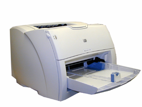
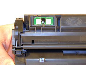
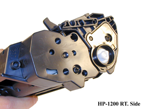
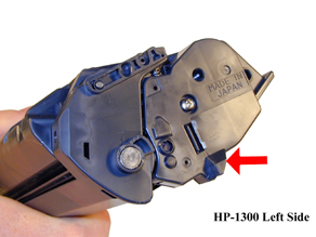
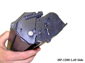
First introduced in March 2003, HP-1300 series of laser printers is based on 20 ppm, 1200dpi Canon engine that comes standard with 16 Meg. memory. The fuser is of the instant on variety and along with a new processor, prints the first page out in under 8 seconds. Two different cartridges are available for the 1300, the Q2613A rated at 2,500 pages, and the Q2613X rated for 4,000 pages. Other than the jump from 17 to 20 ppm, these machines (and cartridges) are basically an HP-1200. The cartridges are almost identical to the 1200, and use the same supplies. The biggest difference is the presence of a chip and some small plastic tabs on the side. These cartridges use the same type chips as the HP-4200/4300. They are the contact type and control the toner low functions. Figures A-E show the physical cosmetic cartridge differences. You can put an HP-1200 toner supply on the front half of a 1300, and it will work. You cannot however test a 1200 cartridge in a 1300 machine because of the notch located next to the chip. The 1300 cartridges cannot be tested in a 1200 because of the new tabs on the sides of the cartridge. I haven’t looked too closely yet, but I think it will be very difficult to modify a 1200 machine to accept a 1300 cartridge.
Although at the time of this writing (April 2003), we are in the initial stages of testing, we do have some information of the functions of the chip. As with the HP-4100/4200/4300 machines if no chip is on the cartridge it will work, but the error message(s) must be cleared first. The toner low functions will not work until a new replacement chip is installed. We are actively working on these chips. Figures F-H show the supplies Status page from a new OEM, a full remanufactured cartridge, and a full cartridge with no chip. Note the page count reflected on the full remanufactured cartridge page. The chip keeps track of all the pages printed. (In this case it has run the OEM plus 1 reman. cycle.) We have not been able so far to get the printer to write “toner out” to the chip.
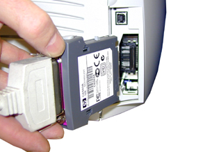
If you test with Anacom smart boxes, they will not work with the current versions. The printer has a "hot" interface that watches both the USB port and the Parallel port. This allows you to have two computers hooked up to it at the same time. One of them can even be a Mac! Unfortunately, it also seems to need specialized information from the new driver before it will accept the print job. In fact, the 1300 has a removable low cost input/output (LIO) adaptor that connects to the back of the printer. For network and wireless connections, this adaptor must be removed. See Figure I
The same complaint I have with the HP-1200 follows here, the paper tray is made too cheaply. I think that the paper tray should be one of the most robust parts in the printer because they have to take so much abuse. These machines as with the HP-1200 have very flimsy paper trays. To be fair, these machines are not built for a network type environment, but since they run at 20ppm, they will surly see some office use (and abuse!).
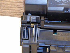
The pin system holding the two halves of the cartridge together is similar to the HP-1200. You will need to cut two small holes cut in the top to get access to the pins. The hole location on these cartridges is almost identical to the 1200, and the same methods you use for the 1200 should work here.
Cartridge troubleshooting as well as running test pages, cleaning pages and some simple printer troubleshooting will be covered at the end of this article.
FIGURE A
FIGURE B
FIGURE C
FIGURE D
FIGURE E
FIGURE F
FIGURE G
FIGURE H
FIGURE I

| Required Tools |
|
Phillips head screw driver.
Small Common screw driver
Dremel type tool with side grinding bit
Plumbers pipe cutter (For replacing the magnetic roller)
| Required Supplies |
|
150g HP-1200 toner for the Q2613A cartridge (2500 pages)
240g HP-1200 toner for the Q2613X cartridge (4000 pages)
New Drum (HP-1200)
Wiper Blade (HP-1200)
Dr. Blade (HP-1200)
Magnetic roller (AX)
Sealing Strip
Cotton Swabs
Isopropyl Alcohol
Drum Padding Powder
| Disassembly |
|
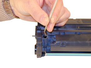
The pins in these cartridges are very similar to the HP-1200 cartridge. The best way to remove them without damaging the cartridge is to cut two small holes in basically the same area as the 1200.
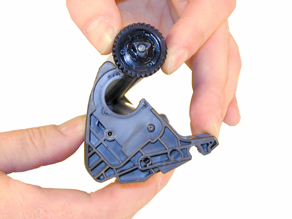
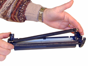
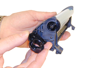
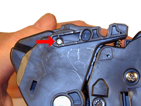
Remove the drum cover by prying up on each end. Note how the spring position so that you it can be replaced later. See Figures 1 & 2
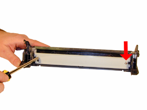
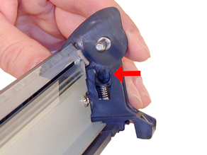
Drill a shallow hole on each side of the cartridge as indicated by figures 3 & 4.
FIGURE 1
FIGURE 2
FIGURE 3
FIGURE 4
Push the pins out with a modified Allen wrench, or a modified spring hook. See Figures 5 & 6
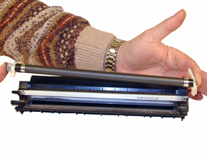
Separate the two halves. See Figure 7
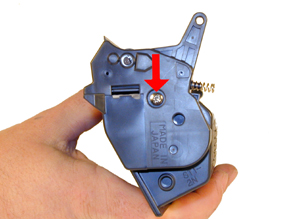
Remove the drum end cap and screw. See Figure 8
FIGURE 5
FIGURE 6
FIGURE 7
FIGURE 8
Remove the drum. See Figure 9. Note the curved plastic piece around the drum. Because of this piece, the drum cannot be removed before the two halves are separated.
Remove the PCR and clean with your standard PCR cleaner. We have been using Nu-Finish for years with out any problems. See Figure 10
Remove the Wiper Blade, the blade is the same as used in the HP-1200. See Figure 11
Clean out the waste toner.
Coat the wiper blade with your preferred lubricant, and re-install. See Figure 12
FIGURE 9
FIGURE 10
FIGURE 11
FIGURE 12
Re-install the cleaned PCR. Note that a new OEM PCR has a small amount of conductive grease on the black (contact) side and what appears to be white lithium grease on the other. See Figures 13 & 14
Re-Install the OPC Drum, end cap, and screw. Slide the hub end onto the drum axle and drop in place. This axle pin is very hard to remove, so this is actually the best way. See Figures 15 & 16
FIGURE 13
FIGURE 14
FIGURE 15
FIGURE 16
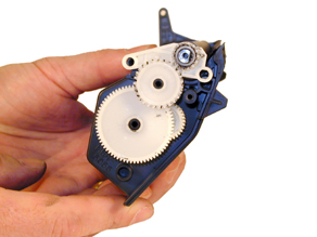
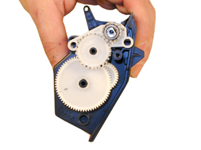
Remove the right side toner hopper end cap. See Figure 17
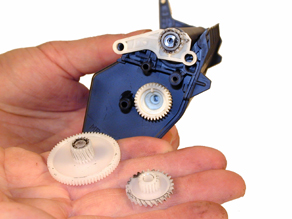
Remove the white gears as shown in Figures 18 & 19. These gears are loose and will fall off if not removed.
Remove the left side end cap. This is the side that houses the Magnetic roller contacts and fill plug. See Figure’s 20 & 21.
FIGURE 17
FIGURE 18
FIGURE 19
FIGURE 20
Remove the magnetic roller assembly. Although not necessary, I find it easier to keep the magnetic roller gears and spacer hubs all together. See Figure 22
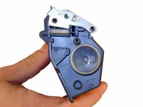
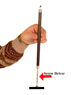
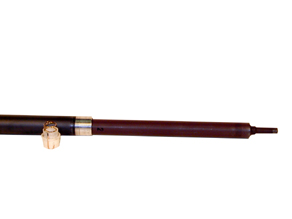
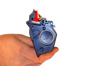
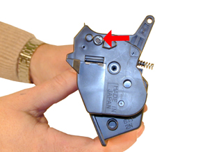
If you are going to replace the magnetic roller sleeve, the contact plate must be removed. It is held in place by a small metal tab that presses against the stationary magnet core. Carefully pry up the tab with a small jeweler’s screwdriver, and remove the plate. Press in from the metal hub side with a small screwdriver to drive the plastic hub out. Make sure when you install the stationary magnet into the new sleeve, that you turn the magnet until it seats in the sleeve. The metal hub and the magnet are keyed. See Figures 23, 24, and 25.
FIGURE 21
FIGURE 22
FIGURE 23
FIGURE 24
Remove the DR. Blade. See Figure 26.
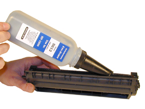
Fill through the Mag roller opening with 150g of 1200 toner for the “A” cartridge, 240g for the “X”. You can fill through the fill hole but unless a seal is installed, you must hold the magnetic roller assy. in place, a very tricky thing to do. See Figure 27
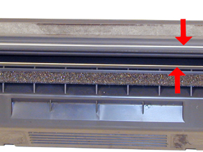
If you are going to seal the cartridge, it should be placed on top of the silver areas shown in Figure 28. The seal tab fits through the right side of the cartridge (fill plug side). Figure 29 shows both the seal exit slot and the fill plug. Figure 30 is a close up of the seal exit slot. Note that it has a rubber gasket that seals off the opening. This port seal must be removed before inserting a seal. Make sure it is put back or the cartridge will leak after the seal has been removed!
Re-install the doctor Blade.
FIGURE 25
FIGURE 26
FIGURE 27
FIGURE 28
FIGURE 29
FIGURE 30
Re-assemble the toner hopper section. Place the Mag. Roller Assy. in the hopper, and install the left end cap first. Align the keyed magnet into the keyed slot. See Figure 31
Install the right side gears, end cap and screw. Align the two posts on the end cap, and the two holes in the white spacer. If all is correct, the end cap should fir flush with the hopper. See Figures 32 & 33
Place the two halves together, make sure that the two springs are aligned, and insert the two pins. Make sure that the pins are slightly pushed in so that they do not interfere with installing the cartridge in the printer. See Figures 34, 35, and 36.
Install the drum cover; make sure the spring is situated correctly. See Figure 37
FIGURE 31
FIGURE 32
FIGURE 33
FIGURE 34
FIGURE 35
FIGURE 36
FIGURE 37


| Troubleshooting |
|
Back grounding: (Gray Streaks) This is usually caused by a dirty/worn out PCR, or a worn out wiper blade.
Light Print: Can be caused by a dirty/worn Magnetic Roller or worn doctor blade.
Solid Black Pages: Bad drum ground contact. Probably from the drum axle shaft to the contact gear inside the drum.
Perfectly straight thin black lines down the page: Scratched drum.
Black dots that repeat every 3": Bad drum, or something is stuck to the drum surface.
Dark black Horizontal lines: Are usually caused by either a bad PCR connection, a pin hole in the PCR, or a pin hole in the drum. These lines normally run about 1/8” thick and can show as few as 4 times/page and as many as 12 times/page.
“Tire Tracks” on the right edge of the page are caused by a worn out drum. (Tire Tracks are what we call a vertical shaded area with lines in it that look like tire tread marks in the sand. This normally happens to OEM drums.
Half the page prints, the other half is blank: The cartridge pin on the blank side is most likely not installed correctly. Remove the pin and re-install making sure that the pin is inserted into both halves
| Running Test Pages |
|
Two pages are available from the front panel of the printer, the Demo Page, and the Configuration Page.
To run the Demo Page, make sure that the ready light is on, and briefly press the GO button. The Demo Page will print out.
To run the Configuration Page, make sure that the ready light is on and press the GO button for 5 seconds. When the GO light turns on, release the button. Two pages with complete printer info including the page count as well as a supplies status page will print out.
| Running the Cleaning Page |
|
To run the Cleaning Page, make sure that the ready light is on and press the GO button for 10 seconds. When all three lights turn on, release the button.
The cleaning process takes about 2 minutes. The cleaning page will stop periodically during the cleaning process. Do not turn the printer off until the process has finished.
| Printer Troubleshooting |
|
As with the 1200, these machines do not have a display panel. All the error codes consist of different pattern of the three lights.
Bottom small light blinking: Cartridge door open, no print cartridge installed, or there is a paper jam.
All three lights on: Fatal error; turn the printer off, and unplug it for 5 minutes. If the error still exists, the printer has a major problem. There is no information yet on what these problems may be. (The service manual has not been released yet).
All three lights blinking: Accessory error; Remove the DIMMs and replace as necessary.
All three lights cycle in sequence: The printer is initializing, the cleaning page is being run, or a job cancel command has been sent.
© 2003 Summit Laser Products, Inc. Any attempt to reproduce any part of these instructions without the written consent of Summit Laser Products, Inc is prohibited. All registered trademarks are the property of their respective owners.
![]()
Contact Summit Laser Products
Toll Free Orders: 800-221-3516
Toll Free Fax: 888-791-9188International Orders: +1-631-218-8376
International Fax: +1-631-218-3285Domestic Sales E-mail: sales@summitlaser.com
International Sales E-mail: export@summitlaser.comTechnical Support: +1-631-218-8376
Technical Support E-Mail: tech@summitlaser.comMail: Summit Laser Products
95 Orville Drive, Bohemia, New York 11716 - USAPlease report any broken links to: webmaster@summitlaser.com
Authorized Summit Laser Distributors
| Ukraine
Distributor SINT Company order@sint-master.com
|
All products on this web site, unless stated otherwise, are independently produced and distributed by Summit Laser, and not by the individual manufacturers of the copiers and printers referenced herein. Use of trade styles and trademarks of the individual manufacturers of the copiers and printers referenced herein are for descriptive purposes only and are not intended to imply any form of endorsement by the individual manufacturers of the refill or supply products offered herein. As such, all items in this catalog are deemed to be construed as “for use in,” “for use with or compatible with,” whether or not stated for each individual item as opposed to the group of items.