

| Home |
New Arrivals!
|
Company Info
|
Publications
|
Special Features
| Contact Us |
 |
|
|
|
|
|
|
HP-2300 Toner Cartridges
DOC-0321
| Overview |
|
Preliminary instruction/information article dated 5/10/2003. A complete set of instructions with printer information will be released as soon as our investigations are concluded, and HP releases the service manual.
Released in April 2003, the HP LaserJet 2300 series of printers are based on a
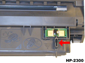
1200dpi, 25ppm Canon engine. As with all the new HP cartridges, these cartridges use a chip to monitor toner low functions. The chip looks very similar to the chips used on the 4300, 4200, and 1300 cartridges. The cartridge for the 2300 is the Q2610A, and is rated for 6000 Pages at 5% coverage. In our initial tests, the new OEM cartridges ranged from 5991 pages to 6212 pages, with densities ranging from 1.50 to 1.52. At first glance the Q2610A cartridge is a smaller version of the 4200 cartridge, but it is actually much closer in design to the 96A (2100) cartridge. The toner however, is very different.
The LaserJet 2300 series of printers use a 266 MHz processor that outputs the first page in less than 10 seconds. With a duty cycle of 30,000 pages, 32Meg memory standard, and pricing starting at $549.00USD, these machines are sure to be very popular. HP has packed a lot of power into a relatively small machine. The cartridges have an internet or “street” price of $119.99USD. (Both prices as of May 2003).
So far the LaserJet 2300 series consists of the following printers:
2300, 2300n, 2300d, 2300dn, 2300dtn, and the 2300L.It should be noted that the 2300L is only rated for 20ppm, and has a duty cycle of 20,000 pages
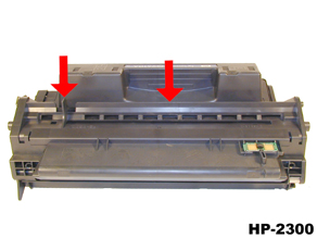
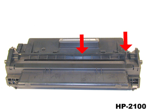
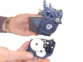
Figures 1-10 show the differences (or similarities) between the 96A cartridge and the Q2610A cartridges,
FIGURE 1
FIGURE 2
FIGURE 3
FIGURE 4
FIGURE 5
FIGURE 6
FIGURE 7
FIGURE 8
FIGURE 9
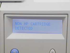
FIGURE 10As with the other new HP cartridges, the chips on these cartridges do not shut down the entire cartridge, they disable the toner low features. The cartridge will run if the chip is removed, but the error message must be cleared first. At the time of writing this article, (May 2003) it is not known if the toner low function will work if the chip is removed. We are still in the initial stages of testing these cartridges. By the time you read this, we should have this as well as other questions answered.
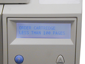
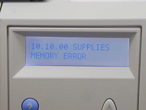
Figures 11-13 Show the display panel when a cartridge is inserted in the printer with a used chip, and with no chip.
FIGURE 11
FIGURE 12
FIGURE 13
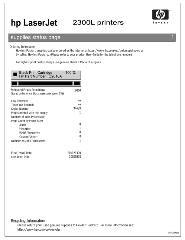
FIGURE 14
(New Cartridge)
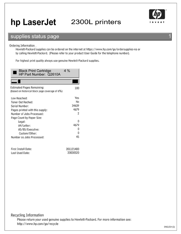
FIGURE 15
(Full Used Cartridge)
FIGURE 16
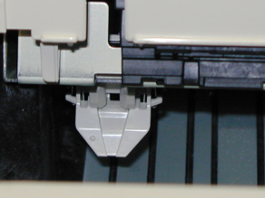
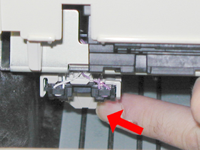
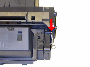
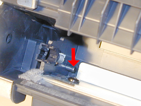
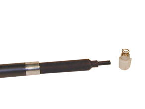
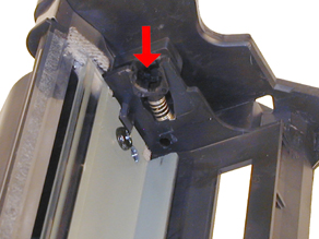
(Full No Chip)There is a small plastic tab located just in front of the chip board on the cartridge. When the cartridge is inserted, this tab engages the chip reader which is on a hinged assembly. If this tab is broken, the reader may not engage properly, and a memory supplies error could occur. (This is the same error you get when the chip is removed.) See Figures 17 and 18
FIGURE 17
FIGURE 18


| Required Tools |
|
Toner approved vacuum.
A small Common screwdriver
A Phillips head screwdriver
Needle nose pliers
Wire Cutters
1/16" or smaller punch
| Required Supplies |
|
Toner 350g HP-2300 type
HP-2300 OPC Drum
HP-2100 Wiper Blade
99% Isopropyl Alcohol
Magnetic Roller Cleaner
Kynar Padding Powder
Nu-Finish car polish
Conductive Grease
| Disassembly |
|
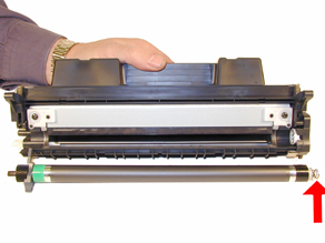
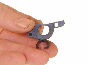
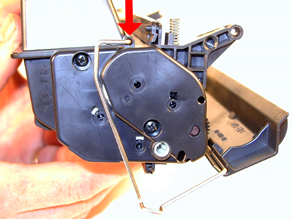
Remove the drum cover by prying the two metal bars out of their holders, and then carefully pry off the spring loaded arm. Be careful not to loose the spring! See Figures 19 & 20
Place the cartridge with the drum side up. Note on each end of the cartridge, there are small silver pins. To separate the two halves these pins must be removed. Like the 96A cartridges, these pins cannot be pulled out, or pushed in from the outside of the cartridge(the wiper blade is in the way). The only way to disassemble the cartridge without damaging it is to push the pins out from the inside. To do this, both the OPC Drum and PCR must first be removed. Replacement pins are available that can be removed from the outside.
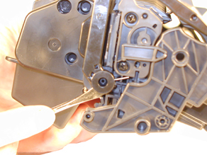
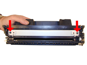
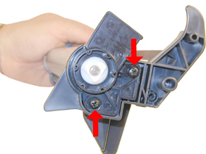
With the pair of needle nose pliers, remove the Metal Axle pin located on the right side of the cartridge. Remove the two screws and the plastic drum bushing from the left side of the cartridge. See Figure’s 21 & 22
FIGURE 19
FIGURE 20
FIGURE 21
FIGURE 22
Remove the Photoconductive Drum being extremely careful not to scratch it. If the drum is in good shape and you plan to re-use it, blow off any toner and debris from drum being careful not to let the air gun come in contact with the drum surface. Do not polish or wipe the drum with a dry cloth since this may scratch the drum. See Figure 23
Carefully remove the Primary Charge Roller (PCR), by gently prying it out of the clips on either end. Be careful as the PCR Holders come loose easily!! Place the PCR aside. See Figure 24
Take the small punch or a small screwdriver, and gently press both of the metal pins out from the inside of the cartridge. To make this process easier, push the pins out 1/2 way, and pull them out from the outside with needle nose pliers or wire cutters. You can also take a normal sized common screwdriver, place the edge against the wiper blade and twist. The pins will move out enough to grab them with pliers from the outside. See Figure’s 25 & 26
FIGURE 23
FIGURE 24
FIGURE 25
FIGURE 26
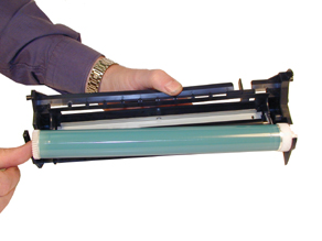
Separate the two halves.
Clean the PCR.
WARNING: Do not clean the OEM PCR with alcohol, as this will remove the conductive coating on the roller. IF the PCR is an after market, follow the cleaning methods recommended by the manufacturer. If the PCR is an OEM, we recommended that it be cleaned with a PCR Cleaner. We have been using Nu-Finish car polish on our OEM PCR's for years with no problems. To clean the roller with the Nu-Finish car polish, apply a small amount and buff with a clean lint free cloth until the roller is clean and shines. If the roller is damaged, or worn out it should be replaced with a new roller.
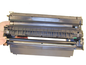
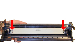
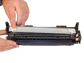
Remove the two screws and the Wiper Blade. Clean the toner out of the waste chamber. See Figure 27
NOTE: Be very careful not to damage or distort the thin Mylar Recovery Blade next to the wiper blade. If this blade is bent or damaged in any way, it should be replaced.
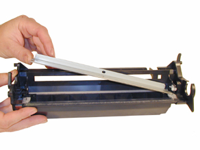
Due to the aggressive nature of the toner used in these cartridges, we recommend that the Wiper Blade be replaced each cycle. Lightly coat the new blade with Kynar drum padding powder. Replace the Wiper Blade into the cartridge. See Figure 28
FIGURE 27
FIGURE 28
NOTE: We do not recommend using Zinc Sterate on this cartridge, as it will stick to the PCR and cause small white voids in the printed characters.
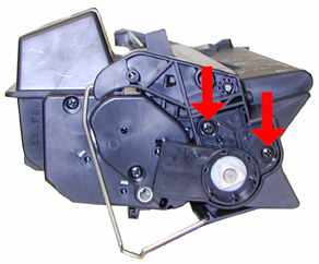
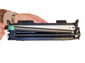
To remove the magnetic roller, first remove the right end cap by removing the two screws. Note the gears in the end cap are held in place. Carefully lift the roller out of the cartridge. Be very careful not to damage the wire contact at the opposite end of the roller. See Figure’s 29, 30 & 31.
FIGURE 29
FIGURE 30
FIGURE 31
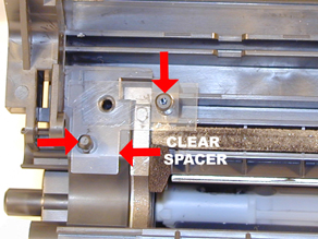
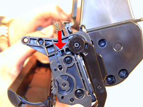
Remove the doctor blade by removing the two screws and lifting it out straight up. When removing this blade, be very careful not to break the alignment pins. These pins keep the doctor blade at the proper distance from the magnetic roller. Make sure that the clear spacers stay in place also! See Figure’s 32 & 33
Vacuum the Toner Supply Chamber thoroughly.
Note that these cartridges do not use Magnetic roller felts. As with all of the newer Canon cartridges, they have small curved magnets to contain any toner that may try to migrate past. See Figure 34
Fill the hopper with 350g of toner through the magnetic roller opening. See Figure 35
FIGURE 32
FIGURE 33
FIGURE 34
FIGURE 35
Inspect the green and black End Caps on the Magnetic Roller Sleeve. Make sure they are not cracked. If they are cracked, they will tear the coating off of the OPC drum. See Figure 36
To change the Magnetic Roller Sleeve, press the magnet from the gear side until the white bushing pops out from the other side. Slide the Stationary Magnet out from the old sleeve and into the new. Place the two end caps, bushing, and gear on the new sleeve; black on the contact side, green on the gear side. Note that the bushing also has a small bushing that fits around the MRS sleeve. So far these small bushings have held up well, but it may cause a problem when the cartridge has been refilled multiple times. Clean the contact spring of the magnetic roller, and the contact-side end cap with the alcohol. Coat the contact side end cap with a small amount of conductive grease. See Figure’s 37, 38, & 39.
FIGURE 36
FIGURE 37
FIGURE 38
FIGURE 39
Install the new Doctor Blade, If the clear spacers are lost, make sure that the new Blade came with them attached. Conversely, if the new Dr. Blade has spacers, make sure that you remove the OEM spacers. Only have one set of spacers should be installed! See Figure 40
Place a small amount of conductive grease on the contact plate of the end cap. Remember, a small amount is more than enough. Too much grease will actually attract toner, and cause problems. Always use conductive grease sparingly. See Figure 41
Install the Magnetic Roller Assembly, Hub, gear, and large end cap. Spin the roller a few times in the proper direction to make sure all is aligned properly. (Make sure the Spring Contact is clean and not bent) See Figure 42
Install the large end cap and two screws. Make sure the gears are clean. See Figure 43.
FIGURE 40
FIGURE 41
FIGURE 42
FIGURE 43
Clean the PCR silver contact ends along with the U-shaped contacts with the Isopropyl Alcohol. These are electrical contacts and must be clean in order for the cartridge to print correctly. Be very careful not to get the alcohol on the rubber part of the PCR as this will remove the conductive coating, ruining the PCR. See Figure 44
Replace the cleaned Primary charge roller. Make sure that the long shaft side is to the black holder side. See Figure 45
FIGURE 44
FIGURE 45
NOTE: IF the PCR is an OEM, proper care of this roller entails cleaning with a PCR cleaner. As stated before, we use NU-Finish on OEM PCR’s, if the PCR is an after market, you should follow the cleaning procedures of the manufacturer.
Coat the OPC Drum with the Kynar, and replace the OPC Drum, metal axle, and plastic drum bushing. Do not install the screws yet. See Figure’s 46, 47, and 48.
Manually spin the OPC drum in the proper direction (towards the edge of the wiper blade); to make sure everything is properly lubricated. If the drum binds, remove it and coat the wiper blade and drum with Kynar again. Once the drums spins properly, install the last two screws in the end cap. See Figure 49
FIGURE 46
FIGURE 47
FIGURE 48
FIGURE 49
Install the drum cover onto the toner hopper. Set the spring as shown in Figure 50, and install the metal bars on both sides. Once installed, release the tail of the spring so that the cover closes properly. See Figure’s 50, 51, & 52.
Place the two halves together, and insert the two silver pins. See Figure 53
FIGURE 50
FIGURE 51
FIGURE 52
FIGURE 53


| Running the Cleaning Page |
|
The cleaning page helps keep the fuser free of toner particles. HP recommends that it be run every time a new cartridge is installed.
Press the SELECT button to open the menus.
Press the UP or DOWN arrows until “CONFIGURE DEVICE” appears on the display.
Press the SELECT button.
Press the UP or DOWN arrows until “PRINT QUALITY” appears on the display.
Press the SELECT button.
Press the UP or DOWN arrows until “CREATE CLEANING PAGE” appears on the display.
Press the SELECT button.
Follow the instructions on the cleaning page to complete the process
| Changing the Printer's Intensity |
|
Press the SELECT button to open the menus.
Press the UP or DOWN arrows until “PRINT QUALITY” appears on the display.
Press the SELECT button.
Press the UP or DOWN arrows until “TONER DENSITY” appears on the display.
Press the SELECT button.
Press the UP or DOWN arrows until the desired setting (1-5) appears on the display. “3” is the default setting
| Printing Test Pages |
|
There are a number of test pages that can be run from the menu. There is a “Menu map”, “Configuration Page”, “Supplies Status Page”, and the “PS or PCL font list”. The Supplies Status Page actually is the best to use. It has Solid Black, Gray Scales, and text.
Press the SELECT button to open the menus.
Press the UP or DOWN arrows until “INFORMATION” appears on the display.
Press the SELECT button.
Press the UP or DOWN arrows until the page you wish to print appears on the display.
Press the SELECT button.
| Cartridge Trouble Shooting |
|
Although these cartridges are new, symptoms pertaining to the HP-2100 should apply here.
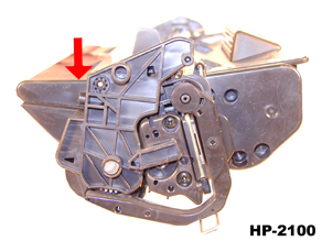
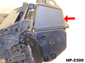
Broken top Fin: If the Plastic fin on the top right side of the cartridge is broken, the display will read INSTALL CARTRIDGE. See the pictures at the beginning of this article for more information.
Memory Supplies Error: this occurs when the chip is either missing, or damaged. The machine will still work, but the SELECT button must be pressed to clear the message.
A dirty or Bad Primary Charge Roller (PCR): this will show on the test print as vertical gray streaks down the page, as a gray background throughout the page, or as ghosting where part of a previously printed area is repeated.
Dirty PCR Connection: This will show as horizontal dark black bars across the page, or as shading throughout the page.
Scratched Drum: This is shown by a very thin, perfectly straight line that runs from the top to the bottom of the test page.
Chipped Drum: This will show as a dot or series of dots that repeat 3 times per page. Any drum defects will repeat 3 times per page based on the drum circumference of 3.66".
Light Damaged Drum: This will show up as a shaded area on the test print that should be white. Again this will repeat 3 times per page.
Worn-Out Drum: This will usually show up as shading on the right side of the page. It will usually start right from the edge of the page, and work in towards the center. The pattern will normally look like tire tracks.
Bad Wiper Blade: This will show as either a gray line approximately 1/8" thick, or as shading across the entire page. In either case there will be a film of toner on the drum surface that matches the defect.
© 2003 Summit Laser Products, Inc. Any attempt to reproduce any part of these instructions without the written consent of Summit Laser Products, Inc is prohibited. All registered trademarks are the property of their respective owners.
![]()
Contact Summit Laser Products
Toll Free Orders: 800-221-3516
Toll Free Fax: 888-791-9188International Orders: +1-631-218-8376
International Fax: +1-631-218-3285Domestic Sales E-mail: sales@summitlaser.com
International Sales E-mail: export@summitlaser.comTechnical Support: +1-631-218-8376
Technical Support E-Mail: tech@summitlaser.comMail: Summit Laser Products
95 Orville Drive, Bohemia, New York 11716 - USAPlease report any broken links to: webmaster@summitlaser.com
Authorized Summit Laser Distributors
| Ukraine
Distributor SINT Company order@sint-master.com
|
All products on this web site, unless stated otherwise, are independently produced and distributed by Summit Laser, and not by the individual manufacturers of the copiers and printers referenced herein. Use of trade styles and trademarks of the individual manufacturers of the copiers and printers referenced herein are for descriptive purposes only and are not intended to imply any form of endorsement by the individual manufacturers of the refill or supply products offered herein. As such, all items in this catalog are deemed to be construed as “for use in,” “for use with or compatible with,” whether or not stated for each individual item as opposed to the group of items.