Remanufacturing
the Xerox DC-212/214 Toner
Cartridge
0327
First released in May 1998, the Xerox DC-212 series of printers
are based on a 12-14ppm 600 dpi Fuji-Xerox engine. These cartridges
use a non-resetable chip that must be changed each cycle. The DC-212
is rated for 12ppm, and the DC-214 is rated for 14ppm.
Xerox currently has two type cartridges available:
Type 1 113R180/113R181 Sold through Xerox dealers
Type 5 113R285/113R287 Sold through retail stores
If the wrong type cartridge is installed, a “J8” code
will be displayed. (Wrong copy cartridge) We will go over how to
tell what type cartridge your machine needs, and what type cartridge
is installed at the end of this article.
Both types are rated for 14,000 pages at 6% coverage, and list
for $373.00 each! While these cartridges look different from most,
they are fairly simple to do, and as you can see, have very nice
margins!
- 820g DC-212 Toner
- New Drum (Highly recommended)
- New Wiper Blade (Highly recommended)
- New Doctor Blade
- Replacement chip
- 99% pure isopropyl alcohol
- cotton swabs
- soft, lint free wipes
- Toner approved vacuum.
- A small Common screw driver
- A spring hook
- Needle nose pliers
- T-10 Torx bit Driver (Same size as the old CX and PC-2000)
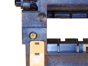
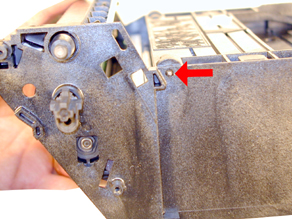
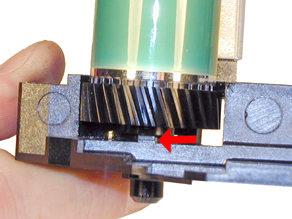
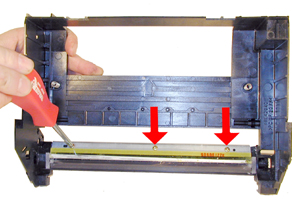
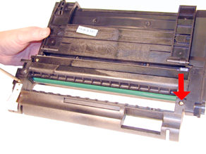
1) On the top of the cartridge, on either side of the handle. Remove
the 2 T-10 Torx screws and the handle. See Figure’s 1 &
2
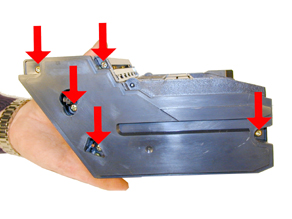
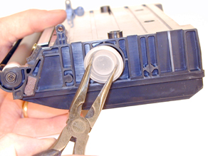
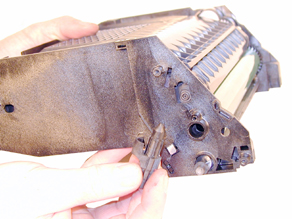
2) On the right side of the cartridge, remove the five screws.
Two or three of these may be Torx. Remove the waste chamber. The
large drum axle pin will come out with the waste chamber. Put it
back in loosely to keep the drum safe. See Figure 3
3) Vacuum the waste chamber clean
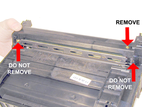
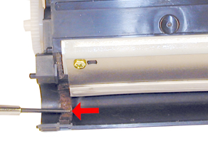
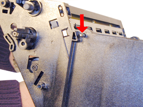
4) Remove the indicated screws from the Corona grid Assembly. Leave
the side and front screws in! Pry the tabs from the side of the
assembly, and remove it. (A spring hook works well for this). See
Figure’s 4 & 5
|
|
Figure
1 |
Figure 2 |
|
|
Figure
3 |
Figure 4 |
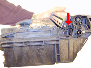
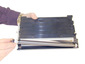
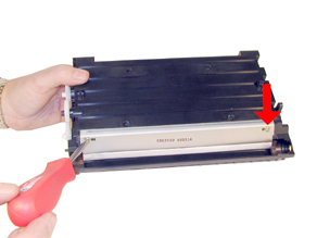
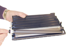
5) There are two large hinge pins, one on each side of the cartridge.
Knock both pins in with a small punch or screwdriver until they
are loose. Remove the supply chamber, and two pins. See Figure’s
6 & 7
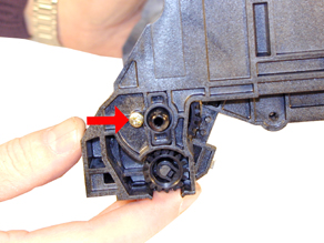
6) Remove the drum axle screws and pins from both sides. The large
pin comes right out, the smaller has two tabs that must be pressed
in before it can be removed. See Figure’s 8 & 9.
|
|
Figure
5 |
Figure 6 |
|
|
Figure
7 |
Figure 8 |
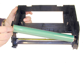
7) Remove the drum. See Figure 10
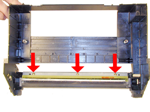
8) Remove the three screws on the wiper blade, and the blade. Clean
out the waste chamber. The auger is locked in place by the gear
and will not fall out. See Figure 11
NOTE: Be very careful not to damage or distort
the thin Mylar Recovery Blade next to the wiper blade. If this blade
is bent or damaged in any way, it should be replaced.
|
|
Figure
9 |
Figure 10 |
|
|
Figure
11 |
Figure 12 |
9) Coat the new wiper blade with your preferred lubricant, and
install the wiper blade and three screws. See Figure 12
10) Remove the fill plug from the toner supply and dump/vacuum out
the remaining toner. Grasp the plug by the center to avoid damaging
the plug. See Figure 13
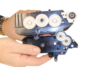
11) Remove the four screws from the gear side end cap, remove the
end cap. Note the gears inside the end cap. See Figure’s 14
& 15
|
|
Figure
13 |
Figure 14 |
|
|
Figure
15 |
Figure 16 |
12) Remove the magnetic roller assembly. See Figure 16
13) Remove the two screws and doctor blade. Clean out all the remaining
toner from the hopper. Scrape a screw driver across the felt seals
so that they “fluff” up. See Figure’s 17 &
18
14) Install the Dr. Blade and two screws. See Figure 19
|
|
Figure
17 |
Figure 18 |
|
|
Figure
19 |
Figure 20 |
15) Install the magnetic roller assembly keyed end (non gear) side
first. See Figure 20
16) Install the end cap. Make sure that all the gears mesh. It
is easiest to spin the mag. roller drive gear while pressing in
the end cap to get all the gears meshed. If the gears are not meshed
properly, the end cap will not sit flush with the cartridge. Install
the screws. See Figure 21
17) Fill the hopper with 820g of DC-212 toner. Check for leaks.
See Figure 22
18) Place the drum in the waste chamber. Install the two axle pins,
large to the non-gear side, and small to the gear side. Screw in
the small axle only, leave the large pin loose. See Figure’s
23 & 24
|
|
Figure
21 |
Figure 22 |
|
|
|
Figure 23 |
Figure 24 |
19) Install the corona wire assembly and screw. Make sure the tabs
from the assembly are aligned. See Figure 25
20) Install the supply chamber and 2 pins. See Figure 26
21) Remove the large axle pin. See Figure 27
22) Install the cleaned waste chamber. See Figure 28
|
|
Figure
25 |
Figure 26 |
|
|
|
Figure 27 |
Figure 28 |
23) Install the large axle pin and screw. See Figure 29
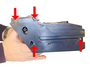
24) Install the four screws on the waste chamber. (two or three
of these will be Torx). See Figure 30
25) Install the handle and two Torx screws. See Figure 31
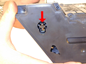
26) Remove the chip assembly from the front edge of the cartridge,
and replace with a new one. See Figure 32 & 33
|
|
Figure
29 |
Figure 30 |
|
|
Figure
31 |
Figure 32 |
|
|
Figure
33
|
This procedure will display the percentage of life left in the
copy cartridge.
1) Press and hold the STOP button. Continue to press the STOP button,
and press the 2 quantity selector button. Release both buttons.
2) A value from 0 to 100 in increments of 5 will display for four
seconds. For example: 65 means that 65% of the cartridge life is
left.
No mention is made of how this determination is made any where
in any manual I could find. Is that percentage based on pages printed?
The amount of toner used? I’m not sure. The chip is shut down
by a low toner signal not by the page count so I would imagine that
the percentage is toner left, but I could not confirm that.
Warning: The following methods call for entering the diagnostic
mode of the machine. Damage can and will occur if the wrong buttons
are pressed while in this mode. Only enter the diagnostic mode if
you are trained, or familiar with repairing Xerox copiers!
If a J8 message is showing on the display, the wrong type of cartridge
(chip) is installed. Enter the diagnostic mode by holding the “0”
button while turning the power on, and then press the “STOP/CLEAR”
button. Wait for the optics to finish initializing before doing
anything further! After the optics are done, press “202, then
“PRINT”. The first 3 digit number displayed is the type
that the machine is set for; the 2nd 3 digit number that flashes
is the type of cartridge installed.
Common Status (Error) Codes
C1 Tray 1 misfeed or no paper
C2 Tray 2 misfeed or no paper
C3 Bypass tray misfeed or no paper
E1 Paper jam between the registration sensor and the exit sensor
E3 Paper jam at exit
E5 Door open
J1 500 pages left in cartridge
J3 Copy cartridge missing or not seated properly
J7 Copy cartridge must be changed
J8 Wrong type of cartridge installed. See text above
U4 Fuser overheat
U5 Fuser under temperature
© 2003-2004 Summit Laser Products, Inc.
Any attempt to reproduce any part of these instructions without the written
consent of Summit Laser Products, Inc is prohibited. All registered trademarks
are the property of their respective owners.
|