Remanufacturing the HP-3500/3700 Black and Color Toner Cartridges
0340
First released in January 2004, the HP color LaserJet 3500/3700 series is based on a 12-16ppm canon print engine. The 3500 and 3700 printers share the same Black cartridge, but use different color cartridges. This canon engine is a single pass (Like the HP-4600) engine capable of up to 2400 DPI when using HPs ImageREt technology.
As our industry has been learning color technology, so has Canon & HP. This series is a streamlined version of the 4600. Two quick examples; There is no longer a toner charging roller in the supply chamber. (They were removed from later HP-4600 cartridges as well). The 3700 weighs 73 lbs, the 4600 weighs 81 lbs. The 3700 is a 16ppm, and the 4600 is 17ppm. That’s a lot of weight reduced for a loss of 1ppm. The cartridge is simpler, as are the machines.
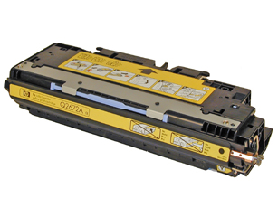
The cartridges used in these machines are as follows. Note that the black is the same for both series.
List* The pricing on all cartridges is current as of October 2005.
Both cartridges are basically the same. The main differences are the amount of toner, and the chips. We are currently investigating if a 3500 cartridge can be converted to a 3700 and visa versa.
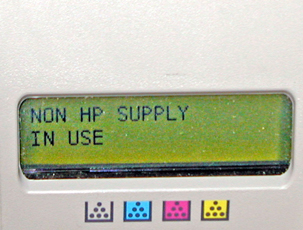
As with most other HP cartridges, these cartridges use a chip. Unlike previous HP color cartridges, the chip does not need to be changed in order for the cartridge to work. The toner low circuitry will be disabled, but after the user presses the green “Select” button, the cartridge will work. It is important to note that if a print job is pending when the “Select” button is pressed to clear the message, that print job will be deleted! If the user presses the “?” button, a lengthy message will show in over 9 different screens. The message states: “ If you believe you purchased an HP cartridge please call the HP fraud hotline. Any printer repair required as a result of using non-HP or unauthorized cartridges is not covered under warranty. HP cannot ensure the accuracy or availability of certain features. Order cartridges #...”
After the message is cleared, it will continually flash on the screen. The printer will work (Minus the toner low functions), but the Non-HP message will rotate with READY on the display. See Figure 1
The machines that use these cartridges are as follows:
HP-3500 Engine
HP Color LaserJet 3500
HP Color LaserJet 3500n
HP Color LaserJet 3550
HP Color LaserJet 3550n
HP-3700 Engine
HP Color LaserJet 3700
HP Color LaserJet 3700dn
HP Color LaserJet 3700dtn
HP Color LaserJet 3700n
HP-3500/3700 Color Printing Theory
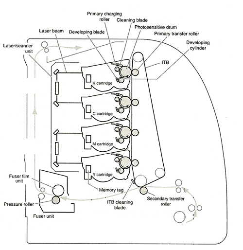
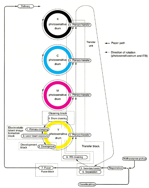
The HP-3500 color printing process is best explained as a series of stages. Figure 2 shows a breakdown of most of the critical printer components as located in the machine.)
In the first stage, the Primary Charge Roller (PCR) places a uniform negative DC voltage on the OPC drum surface. The amount of the negative DC voltage placed on the drum is controlled by the printer’s intensity setting.
In the second stage, the laser beam is fired onto a rotating mirror (called the scanner). As the mirror rotates, the beam is reflected into a set of focusing lenses. The beam then strikes the drums surface, neutralizing the negative charge and leaving a latent electrostatic image on the drum. The areas where the laser did not strike the drum will retain the negative charge. The laser actually has two different controls to keep the strength of the laser light constant. Each color cartridge has its own laser and scanner units.
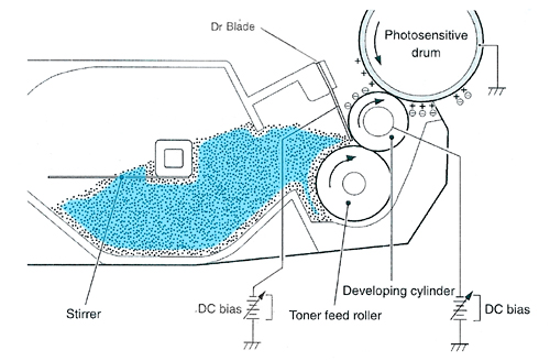
The third or developing stage (See Figure 3) is where the toner is developed on the drum by the developing section (or supply chamber), which contains the toner particles. As the toner stirring blade turns inside the hopper it pushes the toner towards the develop roller. The friction from this process causes a negative potential to develop on the toner. The toner will start to coat the developer roller. At the same time, a negative DC bias voltage is applied to the developer roller. This voltage is controlled by the printer’s intensity setting, and causes either more or less toner to be attracted by the developer roller. This in turn will either increase or decrease the print density. The final amount of toner on the developer roller is controlled by the doctor blade, which uses pressure and a second DC bias voltage to keep the amount of toner on the roller constant. The DC Bias voltage on the doctor blade also keeps the coating of toner on the roller uniform.
As the laser exposed areas of the OPC Drum approach the developer roller, the toner particles are attracted to the drum’s surface due to the opposite voltage potentials of the toner, and laser exposed areas of the OPC drum.
The fourth stage is the Primary transfer stage. (See Figure 4). The first step in the Primary transfer stage is where a positive DC bias voltage is placed on the transfer charging roller which is located directly opposite the OPC drum, and on the back side of the ETB. Each toner cartridge has a separate transfer charging roller. As the ETB passes the transfer charging roller, the positive charge is picked up, and draws the negatively charged toner off the drum onto the paper. This process is repeated for each color cartridge. As the toner piles onto the paper, the positive charge on the paper weakens as the paper runs through each cartridge. For this reason, the charge is increased on the transfer charging roller for each successive color.
The fifth stage is the secondary transfer stage. As the paper reaches the transfer belt, it also runs by the secondary transfer roller. This roller places a positive charge to the paper which causes the toner to transfer from the belt to the paper. After the transfer process is complete, another DC bias voltage is placed on the secondary transfer roller to prevent any toner from sticking to it.
The paper separates from the transfer belt with the help of the static charge eliminator and the stiffness of the paper.
In the sixth stage, the image is then fused on to the paper by the fuser assembly. The fuser Assembly is comprised of the upper heating assembly and lower pressure roller . The lower pressure roller presses the page up into the upper heating assembly which then melts the toner into the paper. The upper heating assembly consists of a flexible sleeve with an induction type heating coil inside. This type of fuser affords “instant on” fusing with little to no wait time, and low power consumption. The lower pressure roller also has a DC bias voltage on it to help hold the toner to the paper, and prevent it from being attracted to the fuser sleeve (offset).
ETB Cleaning:
The ETB belt is cleaned whenever the printer is turned on, when the printer’s covers are closed, at the start of a print job, and after a specific number of pages. Both positive and negative bias voltages are applied to the transfer charge rollers. These voltages repel any residual toner off the ETB and onto the OPC drum where it is cleaned off by the wiper blade. After a print cycle, there is toner with both a negative potential, as well as toner with a positive potential left on the ETB. This is why both voltages are needed.
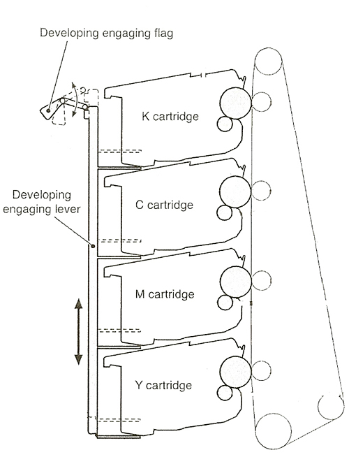
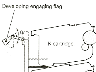
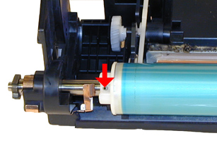
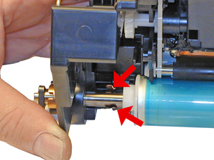
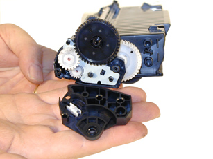
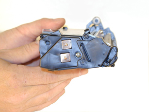
Since the developer roller is always in contact with the OPC drum, precautions are needed in order to make sure that the toner supply chambers are not contaminated with old toner. During ETB cleaning as well as pure monochrome printing, the developer roller should not be in contact with the drum. To accomplish this, the bottom half of the cartridge has been designed to pivot so that the developer roller is moved away from the drum. See Figure 5. A small block is located under the back edge of each cartridge that pushes up to disengage the developer roller.
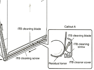
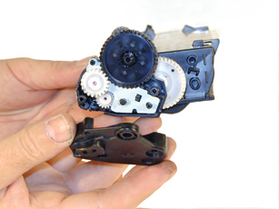
The waste toner cleaned from the belt is moved from the belt through an auger and a conveyor belt to the storage container on the back side of the ITB unit. See Figure 6
| 
|
|
Figure 5 |
Figure 6 |
OPC Drum Cleaning:
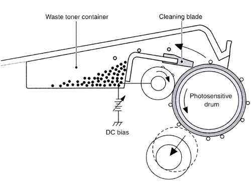
The drum is cleaned after the image is transferred to the paper by the wiper blade. This part is fairly standard; the wiper blade scrapes the toner off the drum, and the recovery blade guides it into the waste chamber. The waste toner is then moved to the back of the waste chamber by the waste toner transfer plate. The difference here is that the PCR needs to be cleaned as well. During normal printing, toner will stick to the PCR. Negative DC bias voltages are applied in varying values to both rollers so that the toner moves from the rollers onto the drum, where the wiper blade will remove it. The PCR cleaning process occurs whenever the printer is turned on, when the printer’s covers are closed, at the start of a print job, and after a specific number of pages. See Figure 7
Toner Level Detection:
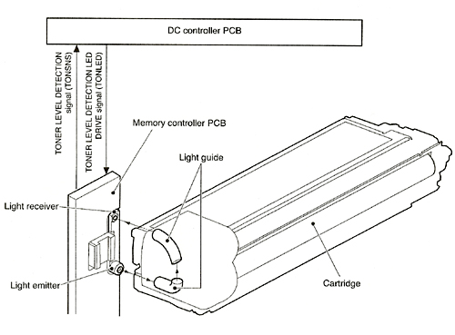
The DC controller detects the amount of toner in each cartridge by the amount of light that is received by the light receiver. During toner level detection, a light is sent out from the emitter, through the guides in the cartridge, and if the toner is low, back to the receiver. If the cartridge is full the receiver will not see any return, and will report the cartridge as full. As the toner is used, more and more light will be received causing the circuit to send this information to the formatter. This will eventually lead to a “toner low” and finally a “toner out” message on the display. See Figure 8
| 
|

|
Figure 7 |
Figure 8 |
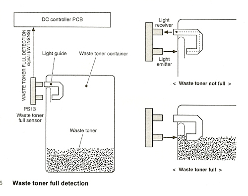
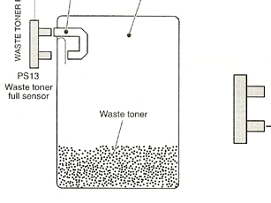
Waste Toner Full Detection:
The DC controller also detects the amount of toner in the ITB waste chamber by the amount of light that is received by the light receiver. Light is sent out from the waste emitter, through the guides in the cartridge, and back to the receiver. Once the waste chamber is full the receiver will not see any return and will report the cartridge as full. The ITB then needs to be replaced. See Figure 9
Printer Calibration:
At the start of all this is the calibration cycle. The printer will calibrate itself whenever the printer is turned on, when a new toner cartridge is installed, and at specific page intervals. Calibration consists of a solid block and halftone of each color being printed to the ETB. As the printed areas get to the top of the belt, a sensor will detect them, measure the density, and adjust the printer accordingly.
The printer also sends registration patterns to both sides of the ITB the two are compared and registration altered accordingly.
Reset Chips:
These Reset chips (or “memory tags” as HP likes to call them), function the same as other HP chips. They control the “Toner Low”, “Toner out”, and “Replace (Color) Cartridge” Messages. Each color cartridge has a specific chip. Be careful not to mix them up. Some aftermarket color chips are now becoming universal for color (One chip for the three colors), check with your vendor. As stated earlier, the chips do not need to be replaced for the cartridge to function, but all the toner low functions will be disabled if they are not. When a used chip is used, the green Select button must be pressed. If the customer presses the “?” button, there is a fairly lengthy message that must be scrolled through before the printer will function. At this point a Non-HP Print cartridge will show on the display. The supplies status page will print, but no cartridge information will be listed. The OEM chips look similar to the other OEM HP chips in that they are the contact type with two pads on the board. See Figure 10.
Due to the nature of color toner, it is not recommended that the initial color of a cartridge be changed. It is virtually impossible to get all the toner out of a cartridge, and if two colors are mixed, the color output will be affected.
Taking test prints, cartridge troubleshooting as well as minor printer troubleshooting will be covered at the end of this article.
| 
|

|
Figure 9 |
Figure 10 |
- 3500/3700 Dedicated Color Toner
- New replacement chip
- Lint free Cloths
- Conductive grease
- Non-hardening silicon caulk (GE, Phenoseal brands work great)
- New Replacement OPC Drum
- Doctor Blade
- Wiper Blade
- Developer rollerFeed Roller
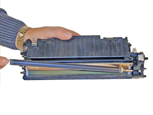
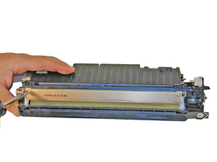
1) Remove the two drum cover axles. Pull out on both sides, the spring will come loose, place it aside. Hold the drum cover back and tape it open so it does not get in the way. The cover can be fully removed, but most likely, the adhesive will become contaminated, and the cover will not stick. If the cover is taped open, it’s not a problem. See Figures 11, 12 & 13
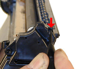
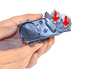
2) There are two pins that hold the two halves together. The pins are sometimes covered with melted plastic. Take a sturdy razor knife and cut away the plastic from around the pins. See Figure 14
| 
|
|
Figure 11 |
Figure 12 |
| 
|

|
Figure 13 |
Figure 14 |
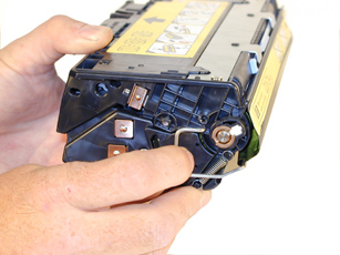
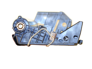
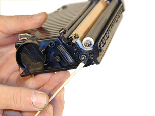
3) Remove the small spring connecting the two halves from the right side with the spring hook. See Figures 15
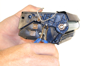
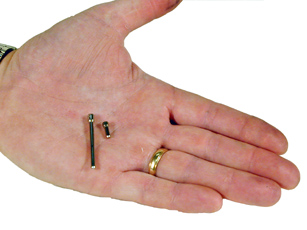
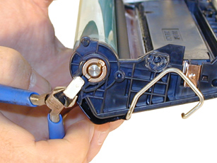
4) With the flush cutting wire cutters, pry the pins out. The left side (gear side) has a very long pin, and the right (Contact side) has a very short pin. See Figures 16 & 17
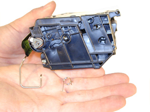
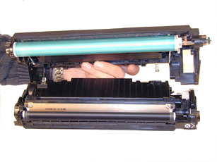
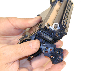
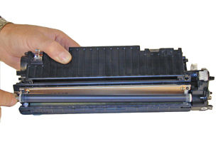
5) Separate the two halves. See Figure 18
| 
|
|
Figure 15 |
Figure 16 |
| 
|
|
Figure 17 |
Figure 18 |
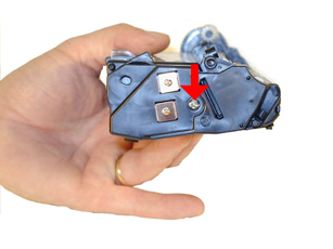
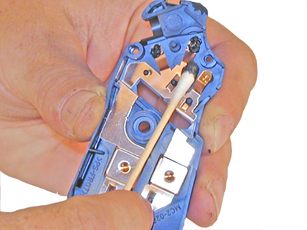
6) On the non-gear side of the drum, there is a small white plastic locking pin. The release tab is on the back edge of the pin. Press in on the tab, and remove the pin. See Figures 19 & 20
| 
|
|
Figure 19 |
Figure 20 |
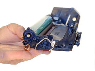
7) Remove the copper bearing from the drum axle. See Figures 21
8) On the gear side, remove the metal pin from the drum axle shaft by gripping it with the wire cutters, and prying it off. Wire cutters are better for this as pliers will slip off. See Figures 22 & 23
9) Carefully remove the drum axle from the gear side. Be careful no to damage the copper contacts when removing it. See Figure 24
| 
|
|
Figure 21 |
Figure 22 |

|

|
Figure 23 |
Figure 24 |
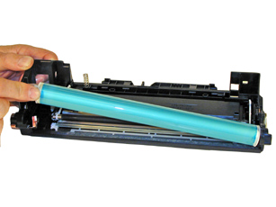
10) Remove the drum. See Figures 25
11) Carefully pry off the long white PCR holders, remove the PCR. See Figure 26
| 
|

|
Figure 25 |
Figure 26 |
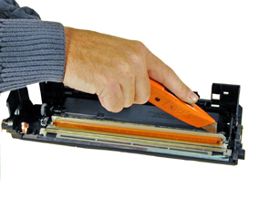
12) With the razor blade, slice along the back edge of the wiper blade to free it from the sealing glue. See Figure 27
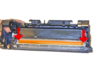
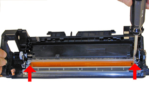
13) Remove the two screws and wiper blade. Be careful not to damage the plastic cover. See Figures 28, & 29
14) Clean out any remaining waste toner from the hopper. This hopper is the reason we do not recommend using a vacuum system to clean them out. The chamber and the access to it is just too small. Clean compressed air is the best way to go, (as long as you have a dust collector of course). See Figure 30
15) Remove any remnants of the old glue with the razor knife.
| 
|
|
Figure 27 |
Figure 28 |
| 
|

|
Figure 29 |
Figure 30 |
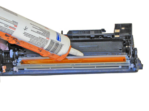
16) Install the new wiper blade and two screws. Seal the back edge of the blade with the silicon to prevent leaks. We recommend either GE 100% Silicon caulk, or Phenoseal brand. Both are the non-drying type, both seal well, and are easily removed for the next cycle. See Figures 31 & 32
| 
|
|
Figure 31 |
Figure 32 |
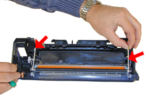
17) Install the cleaned PCR and two white holders. Make sure the white holders are snapped in place. Put a small amount of conductive grease on the black holder end of the PCR. See Figures 33 & 34
| 
|

|
Figure 33 |
Figure 34 |
18) Install the drum. See Figure 35
19) Carefully install the drum axle from the gear side. Watch to make sure the copper contacts are not damaged. See Figures 36 & 37
20) Turn the axle so that the hole in the shaft lines up with the slot in the drum hub. See Figure 38
| 
|

|
Figure 35 |
Figure 36 |
| 
|

|
Figure 37 |
Figure 38 |
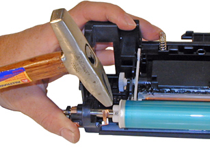
21) Install the metal pin in the axle. Tap it in place with a small hammer. See Figure 39
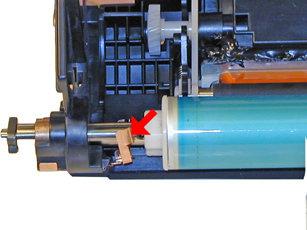
22) Make sure the copper contacts are touching the axle. A bad contact here will cause the loss of the drum ground. And solid color pages may result. See Figure 40
| 
|
|
Figure 39 |
Figure 40 |
23) Install the copper bearing on the non-drive side of the drum. The slots in the bearing should face out. See Figure 41
24) Install the white plastic locking pin so that the tab fits into the slot on the bearing. See Figure 42
| 
|

|
Figure 41 |
Figure 42 |
25) On the toner supply, remove the screw from the right (non-gear) end cap. Lift up on the small locking tab on the top of the end cap, and remove the end cap. See Figures 43 & 44
| 
|
|
Figure 43 |
Figure 44 |
26) On the gear side, remove the two screws, and the end cap. See Figures 45 & 46
| 
|
|
Figure 45 |
Figure 46 |
27) Remove the two gears as shown. See Figure 47
28) Back on the non-gear side remove the two screws, and the alignment plate. See Figures 48 & 49
29) Remove and clean the developer roller. At this time we do not recommend that any chemicals be used to clean it. Just use a lint free cloth to wipe it down. Testing is on-going to see which if any chemicals can be used here. See Figure 50
| 
|
|
Figure 47 |
Figure 48 |
| 
|
|
Figure 49 |
Figure 50 |
30) Remove the two screws on the Dr. Blade, and then the blade. See Figure 51
31) Clean out all remaining toner.
32) The space for the fill hole is there but it is blocked off, there is not a fill hole. Fill the cartridge with the appropriate toner through the dr. blade slot. See Figure 52 & 53
33) If you have a seal, install it now.
34) Install the dr. blade and two screws. If you are re-using the blade, wipe it down with a clean lint free cloth. As with the developer roller, do not use any chemicals. See Figure 54
| 
|

|
Figure 51 |
Figure 52 |
| 
|
|
Figure 53 |
Figure 54 |
35) Install the cleaned developer roller. See Figure 55
36) Place a small amount of conductive grease on the feed roller shaft and the developer roller shaft. Use only a small amount. Too much will attract toner dust and have the opposite effect that is needed. (It will insulate the contact). See Figure 56
| 
|
|
Figure 55 |
Figure 56 |
37) Install the alignment plate and two screws. See Figure 57
38) Clean the grease off all the contacts on the end cap, and replace with fresh conductive grease. Here also, more is not better. Just use a small amount. See Figure 58
| 
|
|
Figure 57 |
Figure 58 |
39) Install the contact end cap and screw. See Figure 59
40) On the gear side, install the two gears as shown. See Figure 60
| 
|

|
Figure 59 |
Figure 60 |
41) Install the end cap and two screws. See Figures 61 & 62
| 
|

|
Figure 61 |
Figure 62 |
42) Make sure the two clear optical toner low windows are clean. See Figure 63
43) Put the two halves together, make sure the hopper spring is positioned correctly. See Figure 64
| 
|
|
Figure 63 |
Figure 64 |
44) Install the two pins, long to the left, and short to the right (contact side). See Figures 65 & 66
| 
|

|
Figure 65 |
Figure 66 |
45) Install the small spring across the two halves. See Figure 67
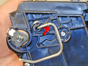
46) Install the drum cover. Press in the two metal arms into their holes, but first place the spring over the left side arm. See Figure 68
| 
|

|
Figure 67 |
Figure 68 |
47) Install the spring as shown. See Figure 69
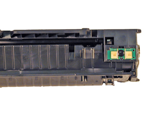
48) Replace the chip. See Figure 70
| 
|
|
Figure 69 |
Figure 70 |
-
Clean Compressed air with approved dust collector system (This is not a cartridge then can be effectively vacuumed)
- Small screw driver (Common Style)
- A Phillips head screwdrivers #1, #0
- Needle Nose Pliers
- Small razor knife
- Jewelers screwdriver set
- Spring hook
Primary Charge Roller (PCR); The primary charge roller if dirty will show on the test print as vertical streaks down the page, or as a background throughout the page. If there is any physical damage, it will repeat at intervals of 26mm. If the back grounding is not all the same color that usually indicates that more than one cartridge has a problem. Use a color chart to determine what cartridges are bad. (Green = cyan and yellow) etc.
A Dirty PCR Connection will result in dark color horizontal bars across the page, or as shading throughout the page. The color of the mark will follow the color of the cartridge
A Scratched Drum will show up as a very thin, perfectly straight line that runs from the top to the bottom of the test page.
A Chipped Drum will result in a dot or series of dots that repeat at 77mm intervals
A Damaged Developer Roller will either leave a mark or a blank spot (depending on the type of damage) at intervals of 38mm.
A Light Damaged Drum will show up as a shaded area on the test print that should be white. Again this will repeat at intervals of 77mm.
A Bad Wiper Blade will result in vertical shaded lines down the page, or as shading across the entire page. In either case there will be a film of toner on the drum surface. The color of the film will follow the color of the cartridge.
If multicolored shaded lines appear down the page, the wiper blade on the ITB has failed, or is dirty.
Some of the more common Printer Error Messages:
10.XX.YY Supplies Error:
For XX = 00 Bad Chip
For XX = 10 Missing chip
For YY = 00 Black cartridge
For YY = 01 Cyan cartridge
For YY = 02 Magenta cartridge
For YY = 03 Yellow cartridge
10.32.00 Unauthorized Supply:
A non-HP cartridge has been installed. This message will stay until the green Select button is pressed. When the Select button is pressed, the first pending print job will be cancelled.
10.92.YY
The cartridges are not making contact with the printer. Poor primary transfer bias contacts, bad high voltage power supply or control signal errors. Open the front door and reset the cartridges in the printer.
For YY = 00 Black cartridge
For YY = 01 Cyan cartridge
For YY = 02 Magenta cartridge
For YY = 03 Yellow cartridge
13.XX.YY Misc. Paper jams
50.X Fuser Error
For X = 1 Low Fuser Temp.
For X = 2 Fuser Warm-up Service
For X = 3 High Fuser Temp.
For X = 4 Bad Fuser
For X = 8 low fuser temperature (sub-thermistor)
For X = 9 high fuser temperature (sub-thermistor)
51.XY Printer Error
For X = 1 Beam Detect Error
For X = 2 Laser Error
For Y = 0 No Color
For Y = K Black
For Y = C Cyan
For Y = M Magenta
For Y = Y Yellow
52.XY Printer Error
For X = 1 Scanner Error
For X = 2 Scanner Startup Error
For X = 2 Scanner Rotation Error
For Y = 0 No Color
For Y = K Black
For Y = C Cyan
For Y = M Magenta
For Y = Y Yellow
54.XX Printer Error
For XX = 1 Humidity environmental sensor error
For XX = 5 Media Sensor Error
For XX = 6 Image Density Sensor out of range
For XX = 11 Yellow Density Sensor error
For XX = 12 Magenta Density Sensor error
For XX = 13 Cyan Density Sensor error
For XX = 14 Black Density Sensor error
For XX = 15 Yellow CPR Sensor error
For XX = 16 Magenta CPR Sensor error
For XX = 17 Cyan CPR Sensor error
For XX = 18 Black CPR Sensor error
For XX = 20 CPR Sensor error
For XX = 21-24 Toner Level Sensors
For XX = 31 Media Sensor calibration failure
For XX = 32 Media Sensor not calibrated
Calibrate Now
If you are experiencing problems with color in OEM cartridges, The “Calibrate Now” feature can be run. This forces a calibration cycle to run. This procedure does not always fix the issue, but it can.
Go in to the Menus until “CONFIGURE DEVICE”
Press the Green “SELECT” Button
Scroll again until “PRINT QUALITY” shows on the display.
Press the Green “SELECT” Button
Scroll through the menus again until “CALIBRATE NOW” shows on the display.
Press the Green “SELECT” Button
The calibration cycle will begin
Configuration Page
Press the “Check” or “Select” button to enter the Menus
Press the “Down Arrow” button to highlight INFORMATION
Press “SELECT”
Press the “Down Arrow” button to highlight PRINT CONFIGURATION
Press “SELECT”.
Supplies Status Page
Press the “Check” or “Select” button to enter the Menus
Press the “Down Arrow” button to highlight INFORMATION
Press “SELECT”
Press the “Down Arrow” button to highlight PRINT SUPPLIES STATUS
Press “SELECT”.
Menu Map Page
Press the “Check” or “Select” button to enter the Menus
Press the “Down Arrow” button to highlight INFORMATION
Press “SELECT”
Press the “Down Arrow” button to highlight Menu Map
Press “SELECT”.
Demo Page
Press the “Check” or “Select” button to enter the Menus
Press the “Down Arrow” button to highlight INFORMATION
Press “SELECT”
Press the “Down Arrow” button to highlight DEMO
Press “SELECT”.
After pressing SELECT the final time, the chosen page will print out. The Configuration page contains all printer information, and color bars. The Supplies Status page contains information about all the consumables.
Repetitive Defect Chart:

|