Remanufacturing the HP LaserJet 2400 Toner Cartridges
0357
Preliminary instruction/information article dated 11/10/2004. A
complete set of instructions with printer information will be released
as soon as our investigations are concluded, and HP releases the
service manual.
Released in October 2004, the HP LaserJet 2400 series of printers
are based on a 1200dpi, 30-35ppm Canon engine. As with all the new
HP cartridges, these cartridges use a chip to monitor toner low
functions. The 2400 cartridge and chip are basically updated versions
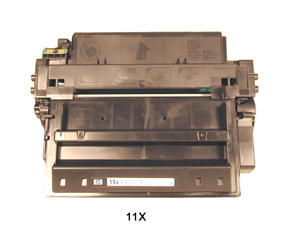
of the 2300 (Q2610A) cartridge. The cartridges for the 2400 are
the Q6511A, rated for 6000 Pages at 5% coverage, and the Q6511X,
rated for 12,000 pages at 5% coverage. Testing is ongoing to see
what (if any) components from the 2300 cartridges will work.
The LaserJet 2400 series of printers use a 400 MHz processor and
the most basic unit has 32Mb of DDR memory. The 2300 has a 266MHz
processor, so this is quite an upgrade. The 2420, 2420d and 2420dn
all have a monthly duty cycle of 75,000 pages/month. The 2430tn
and the 2430dtn have a monthly duty cycle of 100,000 pages/month.
When compared to the 2300 that has a 30,000 page/month duty cycle.
These machines are much more robust. HP has again packed a lot of
power into a relatively small machine. The cartridges have list
prices of $179.30 for the 11A and 301.40 for the 11X. (Both prices
as of November 2004).
So far the LaserJet 2400 series consists of the following printers:
LaserJet 2420, 2420d, 2420dn, 2430tn, 2430dtn.
It should be noted that the 2420 machines are rated for 30ppm,
and the 2430 machines are rated for 35ppm.
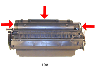
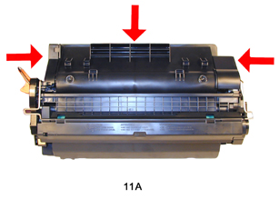
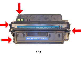
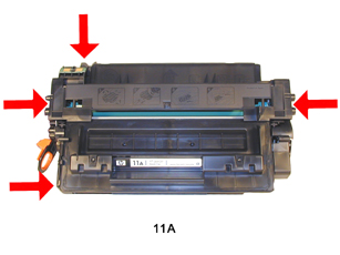
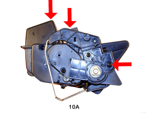
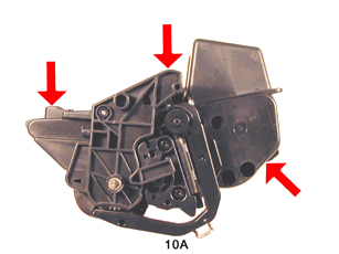
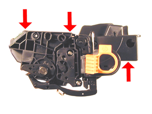
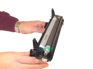
Figures 1-8 show the differences (or similarities) between the
10A (2300) cartridge and the Q6511X cartridges. The cartridges have
been made so that they are not physically interchangeable. Figures
9-12 show the Q5611A cartridge.
|
|
Figure 1 |
Figure 2 |
| 
|
|
Figure 3 |
Figure 4 |
|
|
Figure
5 |
Figure
6 |
|
|
Figure
7 |
Figure
8 |
|
|
Figure
9 |
Figure
10 |
|
|
Figure
11 |
Figure
12 |
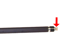
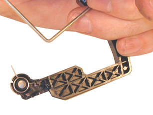
Figure 13 shows the new pull tab for the seal. This tab prevents
the cartridge from being installed unless the seal has been pulled.
(Unless the tab has been separated from the seal of course).
If you look at the boxes, HP is trying to us the last three characters
of the part number as the name of the cartridge. Since these cartridges
will be the 11A, 11X, and the new 1160/1320 cartridges will be the
49A, 49X, it has now become important when your customers order
a cartridge to verify if they want a toner or ink cartridge.
As with all other black HP cartridges, the chips on these cartridges
do not shut down the entire cartridge, they disable the toner low
features. The cartridge will run if the chip is removed, but the
error message must be cleared first. As with past HP chips, the
toner low function is disabled if a used chip is installed. We are
still in the initial stages of testing these cartridges. By the
time you read this, we should have this as well as other questions
answered.
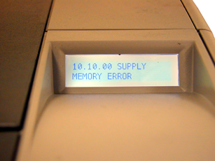
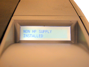
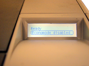
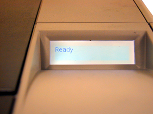
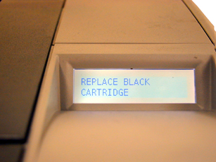
Figures 14-17 Show the display panel when a cartridge is inserted
in the printer with a no chip, figures 18-19 show the display panel
when a cartridge is inserted with a used chip.
|
|
Figure
13 |
Figure
14 |
|
|
Figure
15 |
Figure
16 |
|
|
Figure
17 |
Figure
18 |
|
|
Figure
19 |
|
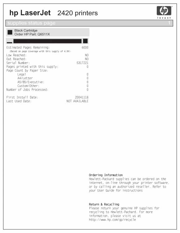
Figures 20-22 show the
Supplies Status Page in the following states:
1) Remove the drum cover by prying the spring loaded arm, and then
carefully pry off the two metal bars out of their holders. The cover
must be in the closed position in order to pry off the spring loaded
arm. Be careful not to loose the spring! See Figures 23 & 24
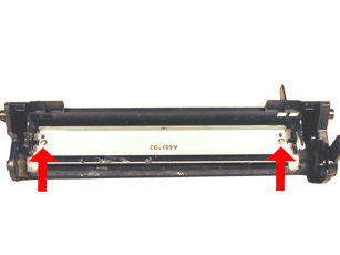
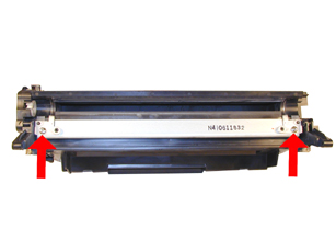
2) Place the cartridge with the drum side up. Note on each end
of the cartridge, there are small silver pins. To separate the two
halves these pins must be removed. Like the 96A/10A cartridges,
these pins cannot be pulled out, or pushed in from the outside of
the cartridge (the wiper blade is in the way). The only way to disassemble
the cartridge without damaging it is to push the pins out from the
inside. To do this, both the OPC Drum and PCR must first be removed.
Replacement pins are available that can be removed from the outside.
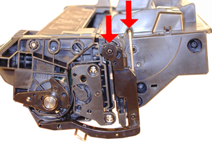
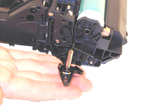
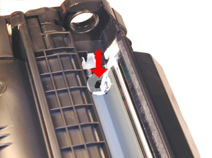
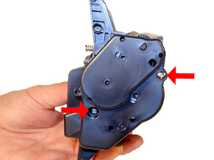
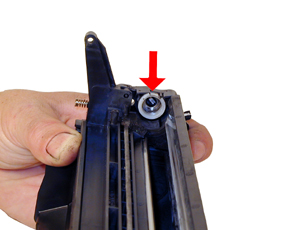
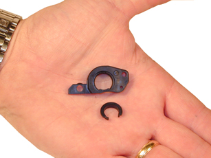
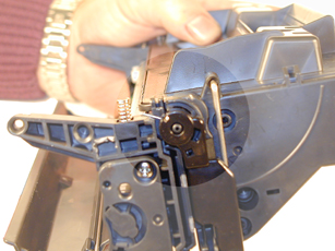
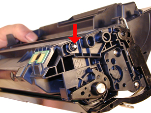
3) With the pair common screwdriver, remove the Metal Axle pin/spring
loaded cover located on the right side of the cartridge. This is
a new type of drum axle pin configuration. It comes out easily enough,
but be careful as it seems somewhat fragile. The opposite side now
has plastic rivets it is not necessary to remove it. See Figure’s
25 & 26
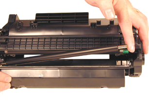
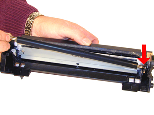
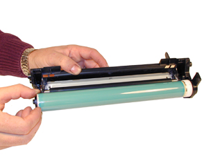
4) Hold the two halves slightly apart and remove the Photoconductive
Drum being extremely careful not to scratch it. If the drum is in
good shape and you plan to re-use it, blow off any toner and debris
from drum being careful not to let the air gun come in contact with
the drum surface. Do not polish or wipe the drum with a dry cloth
since this may scratch the drum. See Figure 27
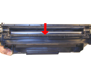
5) Carefully remove the Primary Charge Roller (PCR), by gently
prying it out of the clips on either end. Be careful as the PCR
Holders come loose easily!! Place the PCR aside. See Figure 28
|
|
Figure
25 |
Figure
26 |
|
|
|
Figure
27 |
Figure
28 |
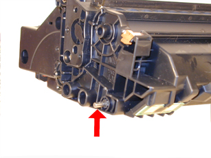
6) Take the Xacto knife with the chisel blade
and cut the pin cover off by slicing it at the side wall of the
cartridge. See Figure’s 29 & 30. This will give you access
to the pins where you can take the small punch or a small screwdriver,
and gently press both of the metal pins out from the inside of the
cartridge. To make this process easier, push the pins out 1/2 way,
and pull them out from the outside with needle nose pliers or wire
cutters. The pins will move out enough to grab them with pliers
from the outside. See Figure’s 31 & 32
7) Separate the two halves.
8) Remove and clean the PCR. Clean the PCR holders with alcohol.
WARNING: Do not clean the OEM PCR with alcohol, as this will remove
the conductive coating on the roller. IF the PCR is an after market,
follow the cleaning methods recommended by the manufacturer. If
the PCR is an OEM, we recommended that it be cleaned with a PCR
Cleaner. We have been using Nu-Finish car polish on our OEM PCR's
for years with no problems. To clean the roller with the Nu-Finish
car polish, apply a small amount and buff with a clean lint free
cloth until the roller is clean and shines. If the roller is damaged,
or worn out it should be replaced with a new roller.
|
|
Figure
29 |
Figure
30 |
|
|
|
Figure
31 |
Figure
32 |
9) Remove the two screws and the Wiper Blade. Clean the toner out
of the waste chamber. See Figure 33
NOTE: Be very careful not to damage or distort the thin Mylar Recovery
Blade next to the wiper blade. If this blade is bent or damaged
in any way, it should be replaced.
10) Due to the aggressive nature of the toner used in these cartridges,
we recommend that the Wiper Blade be replaced each cycle. Lightly
coat the new blade with Kynar drum padding powder. Replace the Wiper
Blade into the cartridge. See Figure 34
NOTE: We do not recommend using Zinc Sterate on this cartridge,
as it will stick to the PCR and cause small white voids in the printed
characters.
11) Place a small amount of conductive grease on the black PCR
holder, install the PCR. Place the waste chamber aside. See Figure
35
|
|
Figure
33 |
Figure
34 |
|
|
|
Figure
35 |
Figure
36 |
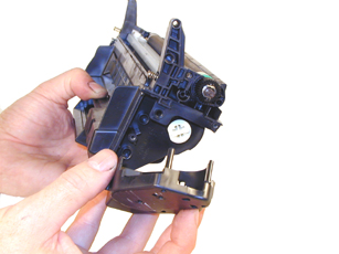
12) To remove the magnetic roller, first remove the right end cap
by removing the two screws. Note the gears in the end cap are held
in place. Carefully lift the roller out of the cartridge. Be very
careful not to damage the wire contact at the opposite end of the
roller. See Figure’s 36, 37 & 38.
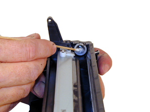
13) Remove the doctor blade by removing the two screws and lifting
it out straight up. When removing this blade, be very careful not
to break the alignment pins. These pins keep the doctor blade at
the proper distance from the magnetic roller. There is a thin bead
on adhesive under the blade. Be sure to keep it clean so that it
stays sticky. See Figure’s 39 & 40
|
|
Figure
37 |
Figure
38 |
|
|
|
Figure
39 |
Figure
40 |
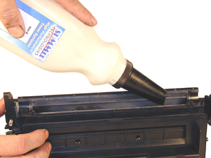
14) Vacuum the Toner Supply Chamber thoroughly.
15) Fill the hopper with 2400 type toner through the magnetic roller
opening. See Figure 41 Use 560g HP-2400 type for 11X, 270g for 11A
(Preliminary weights)
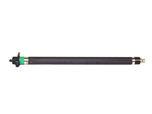
16) Inspect the green and black End Caps on the Magnetic Roller
Sleeve. Make sure they are not cracked. If they are cracked, they
will tear the coating off of the OPC drum. See Figure 42
17) To change the Magnetic Roller Sleeve, press the magnet from
the gear side until the white bushing pops out from the other side.
Slide the Stationary Magnet out from the old sleeve and into the
new. Place the two end caps, bushing, and gear on the new sleeve;
black on the contact side, green on the gear side. Note that the
bushing end cap also has a smaller bushing that fits around the
MRS sleeve. These small bushings may cause a problem when the cartridge
has been refilled multiple times. Clean the contact spring of the
magnetic roller, and the contact-side end cap with the alcohol.
Coat the contact side end cap with a small amount of conductive
grease. See Figure’s 43, 44, & 45.
|
|
Figure
41 |
Figure
42 |
|
|
|
Figure
43 |
Figure
44 |
18) Install the new Doctor Blade. Make sure the adhesive seal has
remained tacky. If not, clean it lightly with a small amount of
alcohol. New replacement seals are being investigated. See Figure
46
19) Install the Magnetic Roller Assembly, Hub, gear, and large
end cap. Spin the roller a few times in the proper direction to
make sure all is aligned properly. (Make sure the Spring Contact
is clean and not bent) In the3 large bushing, there is a smaller
u-shaped bushing. This bushing is similar to the ones used in the
HP-4000 series, and may wear out just as quickly. Testing is ongoing
to determine if this part will need to be replaced. See Figures
47 & 48
|
|
Figure
45 |
Figure
46 |
|
|
|
Figure
47 |
Figure
48 |
20) Install the large end cap and two screws. Make sure the gears
are clean. See Figure 49.
21) Coat the OPC Drum with the Kynar, and replace the OPC Drum
and spring loaded metal axle assembly. See Figure’s 50 and
51.
|
|
Figure
49 |
Figure
50 |
|
|
|
Figure
51 |
Figure
52 |
22) Install the drum cover onto the toner hopper. Set the spring
as shown in Figure 52, and install the metal bars on both sides.
Once installed, release the tail of the spring so that the cover
closes properly. See Figure’s 53 and 54
23) Place the two halves together, and insert the two silver pins.
See Figure 55
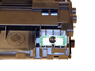
24) Replace the chip. See Figure 56
|
|
Figure
53 |
Figure
54 |
|
|
|
Figure
55 |
Figure
56 |
Running the Cleaning page.
The cleaning page helps keep the fuser free of toner particles.
HP recommends that it be run every time a new cartridge is installed.
1) Press the MENU button to open the menus.
2) Press the UP or DOWN arrows until “CONFIGURE DEVICE”
appears on the display.
3) Press the SELECT button.
4) Press the UP or DOWN arrows until “PRINT QUALITY”
appears on the display.
5) Press the SELECT button.
6) Press the UP or DOWN arrows until “CREATE CLEANING PAGE”
appears on the display.
7) Press the SELECT button.
8) Follow the instructions on the cleaning page to complete the
process
Changing the Printers Intensity (Density)
1) Press the SELECT button to open the menus.
2) Press the UP or DOWN arrows until “PRINT QUALITY”
appears on the display.
3) Press the SELECT button.
4) Press the UP or DOWN arrows until “TONER DENSITY”
appears on the display.
5) Press the SELECT button.
6) Press the UP or DOWN arrows until the desired setting (1-5) appears
on the display. “3” is the default setting
Printing Test Prints
There are a number of test pages that can be run from the menu.
There is a “Menu map”, “Configuration Page”,
“Supplies Status Page”, and the “PS or PCL font
list”. The Supplies Status Page or the Configuration page
are the best to use. They have Solid Black, Gray Scales, and text.
1) Press the SELECT button to open the menus.
2) Press the UP or DOWN arrows until “INFORMATION” appears
on the display.
3) Press the SELECT button.
4) Press the UP or DOWN arrows until the page you wish to print
appears on the display.
5) Press the SELECT button.
Although
these cartridges are new, symptoms pertaining to the HP-2300 should
apply here.
Repetitive defect chart:
4mm Drum
47mm Mag
38mm PCR
Broken Top Fin: If the Plastic fin on the top
right side of the cartridge is broken, the display will read INSTALL
CARTRIDGE.
Memory Supplies Error: this occurs when the chip
is either missing, or damaged. The machine will still work, but
the SELECT “check” button must be pressed to clear the
message.
A dirty or Bad Primary Charge Roller (PCR): this
will show on the test print as vertical gray streaks down the page,
as a gray background throughout the page, or as ghosting where part
of a previously printed area is repeated.
Dirty PCR Connection: This will show as horizontal
dark black bars across the page, or as shading throughout the page.
Scratched Drum: This is shown by a very thin,
perfectly straight line that runs from the top to the bottom of
the test page.
Chipped Drum: This will show as a dot or series
of dots that repeat 3 times per page. Any drum defects will repeat
3 times per page based on the drum circumference of 94mm
Light Damaged Drum: This will show up as a shaded
area on the test print that should be white. Again this will repeat
3 times per page.
Worn-Out Drum: This will usually show up as shading
on the right side of the page. It will usually start right from
the edge of the page, and work in towards the center. The pattern
will normally look like tire tracks.
Bad Wiper Blade: This will show as either a gray
line approximately 1/8" thick or as shading across the entire
page. In either case there will be a film of toner on the drum surface
that matches the defect.
Bad small Magnetic Roller Bushing: When this u-shaped
bushing wears out, gray scale pages, and pages with heavy graphics
will exhibit light and dark line across the page.

| 


