Remanufacturing the HP LaserJet 4250/4350 Toner Cartridges
0358
First
introduced in October 2004, the HP LaserJet 4250 engine is a 45ppm,
1200 dpi engine, the HP LaserJet 4350 is a 55ppm, 1200 dpi engine,
both made by Canon. The Q5942A cartridge is rated for 10,000 pages
at 5%, the Q5942X cartridge is rated for 20,000 pages at 5%. As
with the HP-4200 the chip is mainly controlling the toner low functions
and of course the HP/Non HP cartridge message.
These
instructions cover both the “A” and “X”
cartridges. Unlike the 4200 and 4300 cartridges, these are interchangeable.
Both the A and X cartridges can go into either machine. They will
not however fit into the 4200/4300 machines. Many changes have been
made to prevent this. The only major exception is removing the wiper
blade on the 42X cartridge. The 42X cartridge has a plastic shelf
that must be removed in order to remove the wiper blade. The 42A
cartridge does not have this shelf.
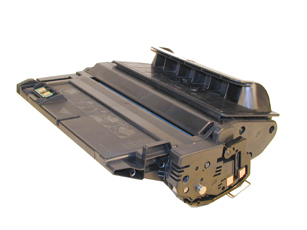
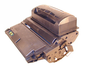
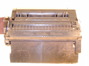
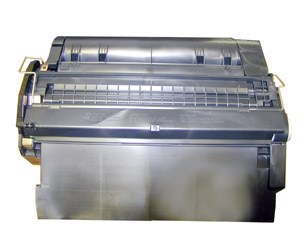
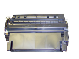
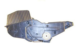
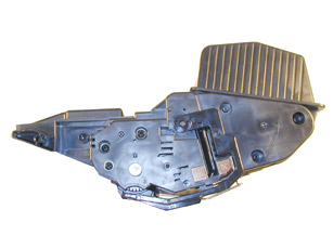
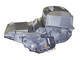
At first glance, these cartridges look very similar
to the 38A/39A cartridges, but upon closer inspection, there are
many subtle differences. There have also been many changes made
to make opening up the cartridge more difficult. HP may publicly
tout that they are friendly to our industry, but more and more their
cartridge design is proving other wise. The following Figures (1-8)
show the difference between the four cartridges.
|
|
| Figure 1: Top of 38A |
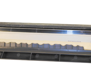
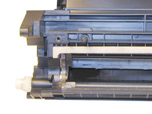
Figure 2: Top of 42A |
|
|
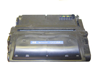
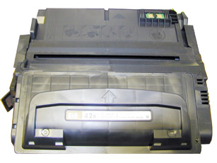
| Figure 3: Bottom of 38A |
Figure 4: Bottom of 42A |
|
|
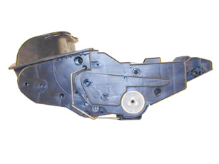
| Figure 5: right side of 38A |
Figure 6: right side of 42A |
|
|
| Figure 7: left side of 38A |
Figure 8: left side of 42A |
|
|
| Figure 9: top of 39A |
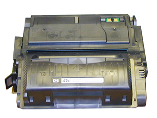
Figure 10: top of 42X |
|
|
| Figure 11: bottom of 39A |
Figure 12: bottom of 42X |
|
|
| Figure 13: right side of 39A |
Figure 14: right side of 42X |
|
|
| Figure 13: left side of 39A |
Figure 14: left side of 42X |
As you can see, HP and Canon seem to have gone
out of their way to design them so that they cannot be made interchangeable
with the 38X/39X cartridges.
Testing is ongoing to see which if any cartridge components fro
the 38A/39A cartridges can be used in these cartridges.
The current machines that use these new cartridges are as follows:
HP-LaserJet 4250
HP-LaserJet 4250n
HP-LaserJet 4250tn
HP-LaserJet 4250dtn
HP-LaserJet 4250dtnsl
HP-LaserJet 4350n
HP-LaserJet 4350tn
HP-LaserJet 4350dtn
HP-LaserJet 4350dtnsl
There is one new setting available in the printer menu, the “OPTIMIZE”
mode. There are three settings possible in this mode.
HIGH TRANSFER: This should be set to “ON” if the paper
being used is of a low quality. The manual does not indicate what
this setting actually does. From the name, it sounds like the settings
of the power supply are changed for the transfer roller, but it
could also be the fuser setting. Hopefully the Service manual when
released will clear this up.
LINE DETAIL: This should be set to “ON” to improve the
appearance of lines on the page.
Polyester based toner; weights to be determined
Replacement drum
Wiper Blade
Doctor Blade
PCR
Magnetic
roller sleeve
- Conductive
Grease
- Tube
of silicon for sealing wiper blade gap. (See Text)
Toner
approved vacuum.
A
small Common screwdriver
A
Phillips head screwdriver
Needle
Nose Pliers
Dremel
tool for removing Wiper Blade
shelf
on 42X cartridges
Magnetic
roller press
1)
Place the cartridge with the toner hopper facing up and away from
you. This will orient the cartridge for right and left sides.
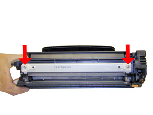
2) Remove the four screws on the left side end cap. See Figure
17
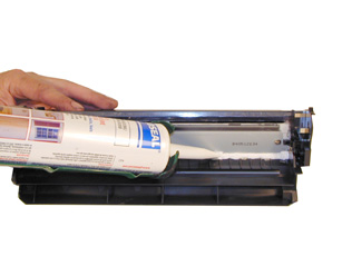
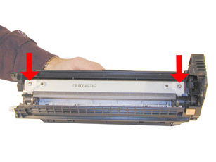
3) Open the drum cover towards the back of the cartridge. Remove
the left side metal bar. See Figure 18
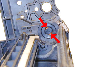
4) Carefully pry off the drum cover plastic arm. The spring will
probably pop off, take care not to loose it. We will go over the
installation at the end of this article. See Figure 19
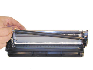
5) Remove the metal bar from the right side, and remove the entire
drum cover assembly. Make sure you put the spring in a safe place.
See Figure 20
|
|
Figure 17 |
Figure
18 |
|
|
Figure 19 |
Figure
20 |
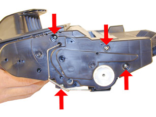
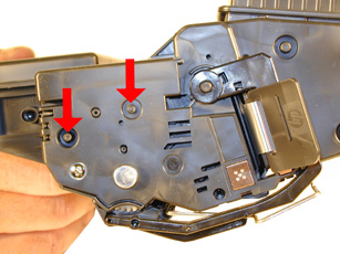
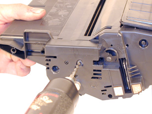
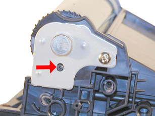
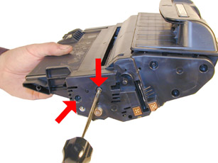
6) Drill out the two plastic
rivets as shown Just drill enough now to allow the end cap to come
free. The rest of the hole will be drilled later. Do not remove
the screw that is holding the recessed metal drum axle pin. See
Figures 21 & 22
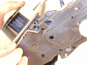
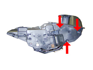
The rest of the right side end cap is held in place by three melted
plastic posts. See Figure 23.
Although there are tools to aid in removing this end cap, we have
found it not necessary. After removing and replacing the waste chamber
a few times, a technician will be much faster than going through
the trouble to remove the end cap.
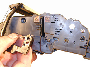
7) Remove the left side end cap from the cartridge. See Figure 24
-
|
|
Figure 21 |
Figure
22 |
|
|
|
Figure
23 |
Figure
24 |
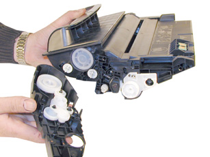
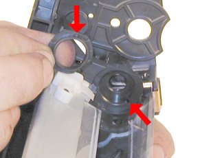
8) Carefully work the waste chamber loose from the right side end
cap. Press in on the metal drum axle pin to help free it. See Figure
25
9) Remove the metal drum axle pin screw and the axle pin. See Figure
26
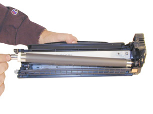
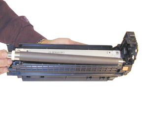
10) Remove the drum. See Figure 27
11) Remove the PCR. See Figure 28
-
|
|
Figure 25 |
Figure
26 |
|
|
|
Figure
27 |
Figure
28 |
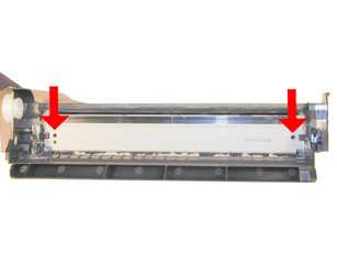
12) Remove the two screws from the wiper blade. See Figure 29
13) With a razor knife, carefully lift up the seal foam and cut
away. This is very sticky stuff, the best way to remove it is to
cut and lift. The wiper blade can be resealed with a good quality
silicon caulk. Make sure you use the type that never dries (Cannot
be painted). See Figure 30
This foam seal is apparently a cheaper way to seal the cartridge
instead of using a foam gasket. Although it is a real pain to remove,
replacing it with silicon will allow you to easily peel it of the
next cycle.
14) At first glance, the 42A/X wiper blade is the same as the 38A/39A.
Further testing is ongoing to confirm this. Due to the high speed
and page counts of these cartridges, we recommend that they be replaced.
*It should be noted that the 42X cartridge has a plastic shelf across
the wiper blade that prevents it from being removed and replaced.
This shelf is best removed by a Dremel type tool with a grinding
bit, or a circular blade bit. We do not recommend that a knife be
used as it is easy to slip and cut yourself. This is identical to
the 39A cartridge. See Figure 31
15) Remove the wiper blade from the cartridge, and clean out the
waste toner.
16) Clean the PCR with your standard PCR cleaner.
17) Install the wiper blade and two screws. See Figure 32
-
|
|
Figure 29 |
Figure
30 |
|
|
|
Figure
31 |
Figure
32 |
18) Seal the back edge of the wiper blade with a good quality silicon
caulk. Use the type that never dries. (Cannot be painted). Let the
caulk dry for a few hours before doing anything else. See Figure
33
19) Install the cleaned PCR. Place a small amount of conductive
grease on the black PCR saddle. Remember, when using conductive
grease, more is not better! See Figure 34
20) Install the drum, drum axle pin and screws. Make sure that
the plastic pin is centered in the oblong hole of the metal axle
pin. (Just like the HP-4000 cartridges) See Figure 35
21) On the supply chamber, carefully pry off the Magnetic roller
(MRS) cover, and remove.
See Figure 36
-
|
|
Figure 33 |
Figure
34 |
|
|
|
Figure
35 |
Figure
36 |
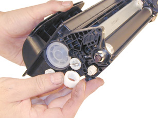
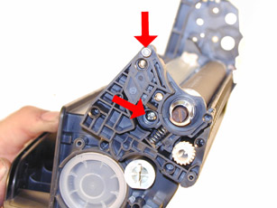
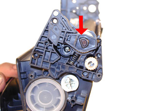
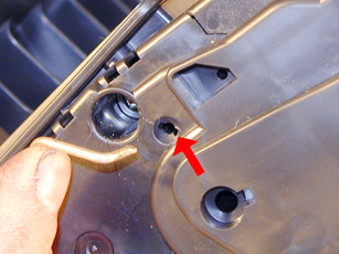
22) Remove the small metal pin from the MRS holder. See Figure 37
23) Remove the MRS drive gear. See Figure 38
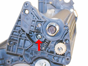
24) Note the location of the spring that sits between the MRS holder
and the hopper. Remove the screw, spring and the holder. See Figure’s
39 & 40
-
|
|
Figure 37 |
Figure
38 |
|
|
|
Figure
39 |
Figure
40 |
25) Remove the MRS assembly. See Figure 41
26) Remove the two Dr. Blade screws and the DR. Blade. Note the
clear spacer that fits in between the blade and the white plastic
spacer. Do not loose this spacer or light print will occur. See
Figure’s 42 & 43
27) Clean out all the remaining toner in the supply hopper.
28) Note the magnetic seals on the MRS and the DB sealing foam.
Make sure both are clean.
See Figure 44
-
|
|
Figure 41 |
Figure
42 |
|
|
|
Figure
43 |
Figure
44 |
29) Note also the new style magnetic roller contact. There are two
copper fingers that fit top and bottom on the Magnetic roller. This
when combined with the new larger diameter of the roller, allow
the cartridge to run at the higher speeds that both machines are
capable of. See Figure 45
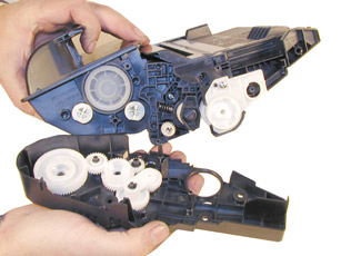
30) There are three separate mixing blades in the toner hopper.
The largest is on the bottom, with the smallest on the top. Each
is driven by its own separate drive gear. See Figure 46
31) The entire upper half of the toner hopper is different in that
is “Floats” on a series of foam seals. The upper half
can be removed from the hopper, but some of the seals will be destroyed.
This may become necessary in order to seal the cartridge, we will
keep you informed as our testing continues.
32) Install the doctor blade and two screws (Make sure that all
the spacers both clear and white are seated correctly!). See Figure
47
33) On the MRS there is a small hub that is keyed into the MRS holder.
Align the hub with its slot and install the hub as well as the entire
MRS assembly. See Figure’s 48 & 49
-
|
|
Figure 45 |
Figure
46 |
|
|
|
Figure
47 |
Figure
48 |
34) Install the holder and spring. See Figure 50
35) Install the screw and the small metal pin. See Figure 51
36) Install the MRS drive gear. See Figure
52
-
|
|
Figure 49 |
Figure
50 |
|
|
|
Figure
51 |
Figure
52 |
37) Install the keyed MRS cover. Make sure that the keyed hole in
the cover matches the keyed end of the magnet in the MRS assembly.
See Figure 53
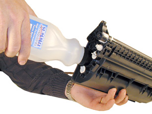
38) Fill with appropriate amount of Polyester based toner. See Figure
54
39) Install the waste section into the fixed end cap on the supply
hopper. This is a tricky process the first few times, but gets much
easier. The best way to do it is to carefully pull the end cap out,
and slide the waste up and in, until everything aligns. For the
first few times, this is definitely easier said than done, but you
will get the hang of it. See Figure 55
40) Install the two screws into the end cap in the holes that were
drilled out previously. See Figure 56
-
|
|
Figure 53 |
Figure
54 |
|
|
|
Figure
55 |
Figure
56 |
41) Install the left side end cap. See Figure 57
42) Install the four screws. See Figure 58
43) Install the metal bars from the drum cover on both sides of
the cartridge. You will have to turn the bars so that the flattened
end of the bars fit into the keyed slots. See Figure 59
44) Install the spring into the drum cover arm as shown. Pull the
upper tail of the spring until it fits into the notch in the arm
hub. See Figure 60
-
|
|
Figure 57 |
Figure
58 |
|
|
|
Figure
59 |
Figure
60 |
45) Install the arm onto the cartridge. Release the spring from
the notch so that the tail fits as shown. See Figure 61
46) Replace the chip on the top of the cartridge. Replacing this
chip will enable the toner low functions of both the cartridge,
and the machine again. See Figure 62
Resetting the Maintenance Kit Counter
Every 200,000 pages, the machine will call for a new maintenance
kit. This kit consists of the Fuser assembly, Transfer roller, paper
pickup rollers, and the paper feed rollers. Once the kit has been
replaced, the counter must be reset.
Turn the printer off and then on.
When “XXX” appears on the display, press and hold the
“SELECT” button. Continue holding the “SELECT”
button until all three control panel lights flash once, and then
stay on. This process can take as much as 10 seconds.
Release the “SELECT” button and press the “UP”
button until NEW MAINTENANCE KIT appears on the display
Press the “SELECT” button to reset the counter
Common Cartridge Problems
OPC Drum: 94mm
Magnetic Roller Sleeve: 55mm
PCR: 38mm
Dirty or Bad Primary Charge Roller (PCR); A bad PCR will normally
cause a gray background, or ghosting. Small defects from the PCR
will repeat every 38mm.
Dirty PCR Connection; This will show as horizontal dark black bars
across the page, or as shadingthroughout the page.
Scratched Drum; This is shown by a very thin, perfectly straight
line that runs from the top to the bottom of the test page.
Chipped Drum; This will show as a dot or series of dots that repeat
3 times per page or every 95mm. Any drum defects will repeat 3 times
per page (94mm).
Light Damaged Drum; This will show up as a shaded area on the test
print that should be white. Again this will repeat 3 times per page.
Tire Tracks; This is normally caused by a bad drum, they normally
show up on the right edge of the page.
Damaged Magnetic Roller Sleeve; A damaged Magnetic Roller Sleeve
will leave a mark that repeats every 55mm.
Printer error Codes
With
these machines, HP has started to move away from number only codes,
most of them are self explanatory in text. There are still a few
however that are part text, and part number. It is those codes that
we will list here.
10.XX.YY Supply Memory Error: An error has occurred in one or more
of the printers supplies. Values of XX and YY are listed below.
XX00 Memory is defective
XX01 memory is missing
YY00 Black print cartridge
This seems to indicate that other supplies such as the staple cartridge
will be chipped also. No other products were available at the time
of this writing to see if they do.
10.32.00 Unauthorized Supply. The printer has detected that a printer
supply is not a genuine HP supply.
No more “Non-HP” message, now it is “Unauthorized
Supply”!!
Error 13.XX.YY: All the error 13 codes deal with paper jams. There
will always be a text message under the number code tell you where
the jam is.
Error 41.X: This code is a Printer error.
Error 50.X: This code is a Fuser error.
Error 51.X: This code is a Printer error.
Error 52.X: This code is a Printer error.
Error 53.XY.ZZ: This code is a Printer Memory error.
Error 59.XY: This code is a Temporary Printer error.
Many of the codes also have sub codes for the “X” and
“Y” values. We will update this instruction as soon
as the service manual is released by HP.
all other codes are self explanatory
Running The Cleaning Page
Press the “MENU” Button
Press the “DOWN ARROW” until CONFIGURE DEVICE appears
Press the “SELECT” Button
Press the “DOWN ARROW” until PRINT QUALITY appears
Press the “SELECT” Button
Press the “DOWN ARROW” until PROCESS CLEANING PAGE appears
Press the “SELECT” Button
Follow the instructions on the cleaning page to complete.
Running Test Pages
Press the “SELECT” Button
Press the “DOWN ARROW” until INFORMATION appears
Press the “SELECT” Button
Press the “DOWN ARROW” until either:
PRINT MENU MAP,
CONFIGURATION PAGE,
SUPPLIES STATUS PAGE, or
PS or PCL FONT LIST appears
Choose the page(s) desired, and
Press the “SELECT” Button

|