Remanufacturing
the HP LaserJet 4350mfp Toner Cartridges
0359
First introduced in January 2005, the HP LaserJet
4345 engine is a 45ppm, 1200 dpi multi-function engine. The new
Q5945A cartridge is rated for 18,000 pages. On the series PDF sheet,
the average yield is stated to be 18,000 pages. “Declared
yield value in accordance with ISO/IEC 19752.” This is the
first time I have seen where the new standard has been used. The
new Q5945A cartridge is very similar internally and externally to
the HP-4300 cartridge the Q1339A with the exception of the chip.
As with all mono black HP cartridges to date the chip is mainly
controlling the toner low functions and of course the HP/Non HP
cartridge message. Before this cartridge arrived I fully expected
to find a new version of the 4250/4350 cartridges. I was very surprised
to find a version of the 4300 instead. One interesting item is that
there is a “drum Life” setting in the machine. The manual
does not state what this is rated for, but when the drum life is
exceeded, even if there is toner left, and the machine is set to
keep printing on toner low, the machine will stop printing until
the cartridge is replaced.
These machines seem to be HP’s first real attempt to gain
a foothold into the multifunction/copier market. While they have
released mfp machines before, this time it looks like they got it
right! They are very aggressively priced, at 1/3 to ½ of
what a similar copier based machine is selling for. HP is also stating
up front that a service contract is not needed for these machines.
Most mfp/copiers are sold along with a service contract. When you
combine that with the lower up front cost, I think these machines
will do well.
The configuration of the base LaserJet 4345mfp machine is as follows:
Touch Screen control panel
50 sheet ADF
100 sheet multi purpose tray
500 sheet input tray
HP Jetdirect Fast Ethernet embedded print server
256 MB DDR RAM
20GB hard drive
One available EIO slot
Available accessories are:
Duplex
Analog Fax
Additional 500 page paper trays
Stand
Stapler/stacker
Bluetooth wireless printer adaptor for walkup printing from a PDA
or Cell Phone.
Software for sending documents to other printers, network folders,
faxes etc.
Software for storage. Allows document management with Microsoft
exchange, Lotus Notes and others.
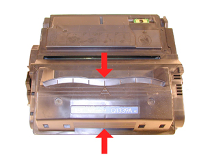
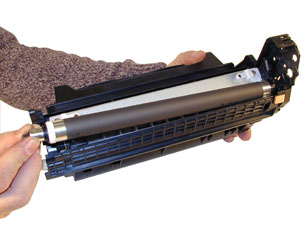
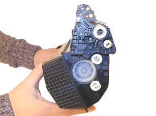
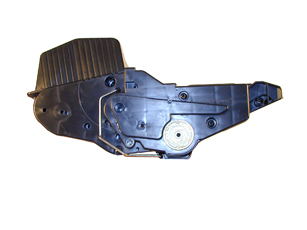
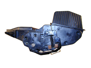
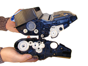
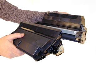
Even though the cartridges are very similar, there are some differences.
The following Figures (1-8) show the difference between the two
cartridges.
|
|
Figure 1 |
Figure 2 |
| 
|
|
Figure 3 |
Figure 4 |
 |
 |
Figure
5 |
Figure
6 |
 |
 |
Figure
7 |
Figure
8 |
Testing is ongoing to see which if any cartridge components from
the 39A
The current machines that use these new cartridges are as follows:
HP-LaserJet 4345mfp
HP-LaserJet 4345x mfp
HP-LaserJet 4345xs mfp
HP-LaserJet 4345xm mfp
Printer usage, as well as some common printer/cartridge problems
will be covered at the end of this article.
-
Polyester based toner; 1024g for the OEM, aftermarket weights
to be determined
-
Conductive
Grease
-
Replacement
drum
-
Wiper
Blade
-
Doctor
Blade
-
PCR
-
Magnetic
roller sleeve
-
Tube
of silicon for sealing wiper blade gap. (See Text)
-
Toner approved vacuum.
-
A small Common screw driver
-
A Phillips head screwdriver
-
Needle nose pliers
-
Dremel tool for removing Wiper Blade shelf on 42X cartridges
-
Magnetic roller pres
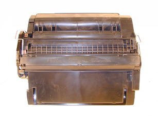
1) Place the cartridge with the toner hopper facing up and towards
you. This will orient the cartridge for right and left sides.
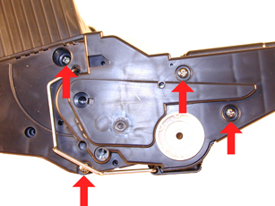
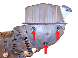
2) Remove the four screws on the right side end cap. See Figure
9
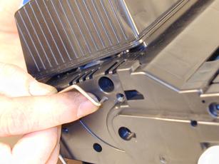
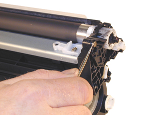
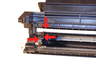
3) Open the drum cover towards the back of the cartridge. Remove
the right side metal bar. See Figure 10
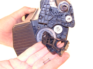
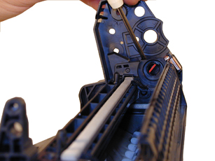
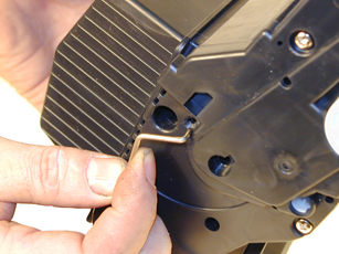
4) On the opposite side of the cartridge, carefully pry off the
drum cover plastic arm. The spring will probably pop off, take care
not to loose it. We will go over the installation at the end of
this article. See Figure 11
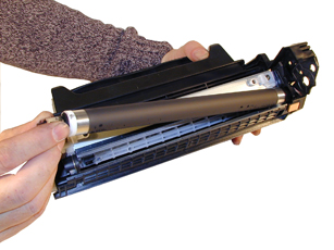
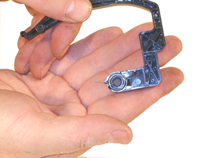
5) Remove the metal bar from the left side, and remove the entire
drum cover assembly. Make sure you put the spring in a safe place.
See Figure 12
|
|
Figure 9 |
Figure 10 |
| 
|

|
Figure 11 |
Figure 12 |
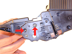
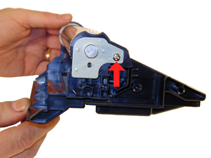
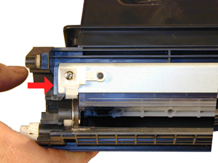
6) Remove the two screws from the left end cap. See Figures 13
The rest of the left side end cap is held in place by three melted
plastic posts. See Figure 14. Although there are tools to aid in
removing this end cap, we have found it not necessary. After removing
and replacing the waste chamber a few times, a technician will be
much faster than going through the trouble to remove the end cap.
7) Remove the right side end cap from the cartridge. Note that the
gears do not come off the end cap. See Figure 15
8) Carefully work the waste chamber loose from the left side end
cap. Press in on the metal drum axle pin to help free it. See Figure
16
|
|
Figure
13 |
Figure
14 |
 |
 |
Figure
15 |
Figure 16 |
9) Remove the metal drum axle pin screw and the
axle pin. See Figure 17
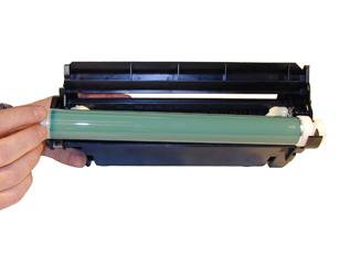
10) Remove the drum. See Figure 18
11) Remove the PCR. See Figure 19
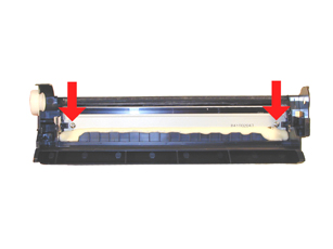
12) Remove the two screws from the wiper blade. See Figure 20
|
|
Figure
17 |
Figure
18 |
|
|
|
Figure
19 |
Figure
20 |
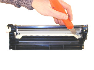
13) With a razor knife, carefully lift up the
seal foam and cut away. This is very sticky stuff, the best way
to remove it is to cut and lift. The wiper blade can be resealed
with a good quality silicon caulk. Make sure you use the type that
never dries (Cannot be painted). See Figure 21
This foam seal is apparently a cheaper way to seal the cartridge
instead of using a foam gasket. Although it is a real pain to remove,
replacing it with silicon will allow you to easily peel it of the
next cycle.
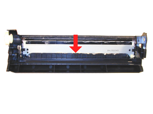
Like the Q1339A cartridge, this cartridge has a plastic shelf across
the wiper blade that prevents it from being removed and replaced.
This shelf is best removed by a Dremel type tool with a grinding
bit, or a circular blade bit. We do not recommend that a razor knife
be used as it is easy to slip and cut yourself. This is identical
to the 39A cartridge. See Figure 22
14) Due to the high speed and page counts of these cartridges,
we recommend that the wiper blades be replaced.
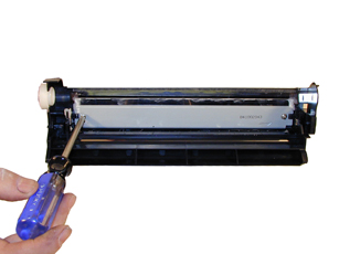
15) Remove the wiper blade from the cartridge, and clean out the
waste toner. See figure 23
16) Clean the PCR with your standard PCR cleaner.
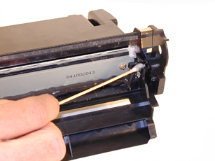
17) Install the wiper blade and two screws. See Figure 24
|
|
Figure
21 |
Figure
22 |
|
|
|
Figure
23 |
Figure
24 |
18) Seal the back edge of the wiper blade with a good quality silicon
caulk. Use the type that never dries. (Cannot be painted). Let the
caulk dry. See Figure 25
19) Install the cleaned PCR. Place a small amount of conductive
grease on the black PCR saddle. Remember, when using conductive
grease, more is not better! See Figure 26
20) Install the drum, drum axle pin and screws. Make sure that
the plastic pin is centered in the oblong hole of the metal axle
pin. (Just like the HP-4000 cartridges) See Figure 27
21) On the supply chamber, carefully pry off the Magnetic roller
(MRS) cover, and remove. See Figure 28
|
|
Figure
25 |
Figure
26 |
|
|
|
Figure
27 |
Figure
28 |
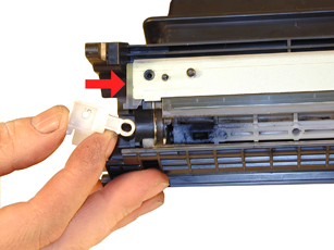
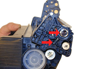
22) Remove the small metal pin from the MRS holder. See Figure
29
23) Remove the MRS drive gear. See Figure 30
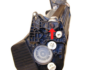
24) Note the location of the spring that sits between the MRS holder
and the hopper. Remove the screw, spring and the holder. See Figure’s
31 & 32
|
|
Figure
29 |
Figure
30 |
|
|
|
Figure
31 |
Figure
32 |
25) Remove the MRS assembly. See Figure 33
26) Remove the two Dr. Blade screws and the DR. Blade. Note the
clear spacer that fits in between the blade and the white plastic
spacer. Do not loose this spacer or light print will occur. The
screws for this blade are longer than the screws used in the rest
of the cartridge. See Figure’s 34 & 35
27) Clean out all the remaining toner in the supply hopper.
28) Note the magnetic seals on the MRS and the DB sealing foam.
Make sure both are clean. See Figure 36
|
|
Figure
33 |
Figure
34 |
|
|
|
Figure
35 |
Figure
36 |
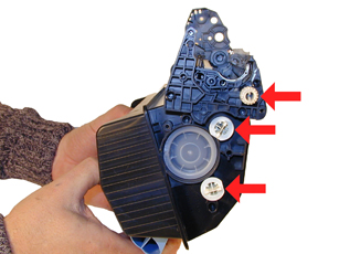
29) Note also the new style magnetic roller contact.
There are two copper fingers that fit top and bottom on the Magnetic
roller. This when combined with the new larger diameter of the roller,
allow the cartridge to run at the higher speeds that both machines
are capable of. One contact has been colorized for easier identification.
See Figure 37
30) There are three separate mixing blades in the toner hopper.
The largest is on the bottom, with the smallest on the top. Each
is driven by its own separate drive gear. See Figure 38
31) The upper mar roller section of the toner hopper is different
in that is “Floats” on a series of foam seals. The upper
half can be removed from the hopper, but some of the seals will
be destroyed. This may become necessary in order to seal the cartridge,
we will keep you informed as our testing continues. The foam isolates
the mag roller from the vibrations of the mixing augers, and allows
smoother prints.
32) Install the doctor blade and two screws (Make sure that all
the spacers both clear and white are seated correctly!). Be sure
to use the longer screws! See Figure 39
|
|
Figure
37 |
Figure
38 |
|
|
|
Figure
39 |
|
33) On the left side of the mar roller there is a small hub that
is keyed into the MRS holder. Align the hub with its slot and install
the hub as well as the entire MRS assembly. They have been colorized
for easier identification.
See Figure’s 40 & 41
34) Install the holder and spring. See Figure 42
35) Install the screw and the small metal pin. See Figure 43
|
|
Figure
40 |
Figure
41 |
|
|
|
Figure
42 |
Figure
43 |
36) Install the MRS drive gear. See Figure 44
37) Install the keyed MRS cover. Make sure that the keyed hole
in the cover matches the keyed end of the magnet in the MRS assembly.
See Figure 45
38) Fill with appropriate amount of Polyester based toner. See
Figure 46
39) Install the waste section into the fixed end cap on the supply
hopper. This is a tricky process the first few times, but gets much
easier. The best way to do it is to carefully pull the end cap out,
and slide the waste up and in, until everything aligns. For the
first few times, this is definitely easier said than done, but you
will get the hang of it. See Figure 47
|
|
Figure
44 |
Figure
45 |
|
|
|
Figure
46 |
Figure
47 |
40) Install the two screws into the end cap in the holes that were
drilled out previously. See Figure 48
41) Install the left side end cap. See Figure 49
42) Install the four screws. See Figure 50
43) Install the metal bars from the drum cover on both sides of
the cartridge. You will have to turn the bars so that the flattened
end of the bars fit into the keyed slots. See Figure 51
|
|
Figure
48 |
Figure
49 |
|
|
|
Figure
50 |
Figure
51 |
44) Install the spring into the drum cover arm as shown. Pull the
upper tail of the spring until it fits into the notch in the arm
hub. See Figure 52
45) Install the arm onto the cartridge. Release the spring from
the notch so that the tail fits as shown. See Figure 53
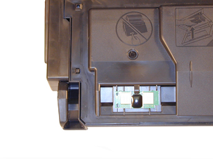
46) Replace the chip on the top of the cartridge. Replacing this
chip will enable the toner low functions of both the cartridge,
and the machine again. See Figure 54
|
|
Figure
52 |
Figure
53 |
|
|
|
Figure
54 |
|
OPC Drum: 94mm
Magnetic Roller Sleeve: 55mm
PCR: 38mm
Common Cartridge Problems
Dirty or Bad Primary Charge Roller (PCR); A bad PCR will normally
cause a gray background, or ghosting. Small defects from the PCR
will repeat every 38mm.
Dirty PCR Connection; This will show as horizontal dark black bars
across the page, or as shading throughout the page.
Scratched Drum; This is shown by a very thin, perfectly straight
line that runs from the top to the bottom of the test page.
Chipped Drum; This will show as a dot or series of dots that repeat
3 times per page or every 95mm. Any drum defects will repeat 3 times
per page (94mm).
Light Damaged Drum; This will show up as a shaded area on the test
print that should be white. Again this will repeat 3 times per page.
Tire Tracks; This is normally caused by a bad drum, they normally
show up on the right edge of the page.
Damaged Magnetic Roller Sleeve; A damaged Magnetic Roller Sleeve
will leave a mark that repeats every 55mm.
Touch “MENU” on the control panel
Scroll and touch “CONFIGURE DEVICE”
Touch “PRINT QUALITY”
Touch “PROCESS CLEANING PAGE”
This process will take 2½ minutes to complete
Touch “MENU” on the control panel
Touch “INFORMATION”
Scroll down until either:
MENU MAP,
CONFIGURATION PAGE,
SUPPLIES STATUS PAGE, or
PS or PCL FONT LIST appears
Choose the page(s) desired
Every 200,000 pages, the machine will call for a new maintenance
kit. This kit consists of the Fuser assembly, Transfer roller, paper
pickup rollers, and the paper feed rollers. Once the kit has been
replaced, the counter must be reset.
Touch “MENU” on the control panel
Scroll and touch “CONFIGURE DEVICE”
Scroll and touch “RESETS”
Touch “RESET SUPPLIES”
Touch “NEW MAINTENANCE KIT”
The counter is reset
There is also an ADF maintenance kit that should be replaced every
90,000 pages (On the ADF only). Do the same as above but choose
the NEW DOCUMENT FEEDER KIT under RESET SUPPLIES
With these machines, HP has started to move away from number only
codes, most of them are self explanatory in text. There are still
a few however that are part text, and part number. It is those codes
that we will list here.
10.XX.YY Supply Memory Error: An error has occurred in one or more
of the printers supplies. The chip is now called an “E-Label”
and the machine cannot communicate with one of them. This could
be the toner cartridge or the Staple cartridge.
The “Non-HP supply installed” message is back. The
4250/4350 uses “Unauthorized Supply”
Error 13.XX.YY: All the error 13 codes deal with paper jams. There
will always be a text message under the number code tell you where
the jam is. These messages are very specific.
Error 41.X: This code is a Temporary Printer error.
Error 50.X: This code is a Fuser error.
Error 51.X: This code is a Temporary Printer error.
Error 52.X: This code is a Temporary Printer error.
Error 53.XY.ZZ: This code is a Printer Memory error.
Error 59.XY: This code is a Temporary Printer error.
All of these temporary printer errors can be cleared by turning
the machine off an on. No other information on what they actually
mean is available.
Many of the codes also have sub codes for the “X” and
“Y” values. We will update this instruction as soon
as the service manual is released by HP.
all other codes are self explanatory

|