 |
| Remanufacturing the Samsung CLP-500/550 Black and Color Toner cartridges |
Remanufacturing the Samsung CLP-500/550 Black and Color Toner cartridges
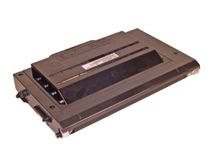
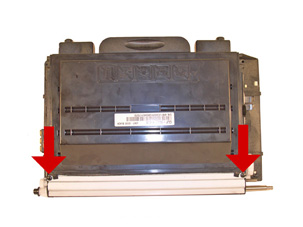
First introduced in October 2003, the Samsung CLP-500 series of printers is based on a 21ppm black/5ppm, 600DPi color Samsung print engine. These printers were the first to have a list price of under $500.00 USD. They became very popular, very fast. No chips are used to shut the cartridges down after toner low is reached. There are however 2 resistors on the fill plug side. The inner is a 56 Ohm and the outer is a 7.5KOhm resistor. These resistors must be checked each cycle. The outer 7.5k resistor will blow and needs to be replaced. Service manuals are impossible to find on these machines, but my guess is that the other resistor is there as a cheap form of identification. These two resistors = Samsung, another set of different values would represent another company. Samsung has used this method before. No other companies that I know of ever used this particular engine though, so this is pure speculation. When the CLP-510 was released, the cartridges had installed chips that need to be replaced. The Samsung CLP-510 series as well as the Xerox Phaser 6100 are based on the newer engine. While the cartridges seem similar, there are differences, and they will be covered in a future article. The 500 series does have a circuit board on it, but this board does not contain a chip. Instead it houses a series of zener diodes that regulate the developer roller bias voltage. This board should never need to be replaced. Care needs to be taken when removing it so it doesn't get damaged, but zener diodes are fairly durable. There are seven user replaceable cartridges in these machines, 4 toner cartridges, a drum unit, Transfer unit and the waste container. The drum and waste collector will also be covered in a future article. The toner cartridges are all installed through the left cover (with the display in front of you). The drum unit and transfer belt are installed through the top cover, and the waste container is installed through the front cover. Each cartridge has its own slot. From top to bottom, they are: Black, Yellow, Magenta, and Cyan. If they are installed in the wrong slot, the left cover will not close. Note the different back tabs for each color cartridge. See Figure A The machines that use these cartridges are as follows: Samsung CLP-500 Samsung CLP-500N Samsung CLP-550 Samsung CLP-550N Samsung CLP-500 Cartridges CLP-500D7K/XAA Black 7,000 pages at 5% $129.00 List* CLP-500D5C/XAA Cyan 5,000 pages at 5% $149.00 List* CLP-500D5M/XAA Magenta 5,000 pages at 5% $149.00 List* CLP-500D5Y/XAA Yellow 5,000 pages at 5% $149.00 List* CLP-500RB/XAA Drum 50,000 Mono/12,500 Color $199.00 List* CLP-500WB/XAA Waste Container 12,000 mono/3,000 Color $39.00 List CLP-500RT/XAA Transfer belt 50,000 Mono/12,500 Color $199.00 list* • The pricing on all cartridges is current as of May 2005. As you can see from the pricing above, replacing multiple cartridges can quickly get very costly. Buying these machines may be inexpensive, but using them certainly isn't! Our industries favorite kind of pricing system! These machines use the single pass print system similar to the HP-4600. Once service manuals are available, we will update this instruction and add a print theory section. But basically, it is the same as far as we can tell as the 4600. Taking test prints, cartridge troubleshooting as well as minor printer troubleshooting will be covered at the end of thiS article.
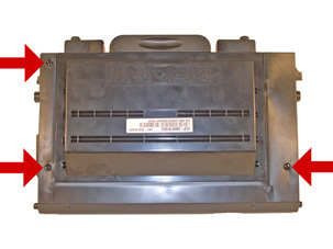
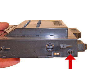
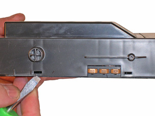
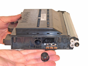
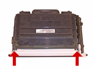
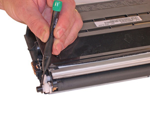
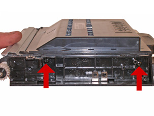
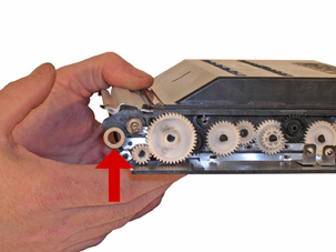
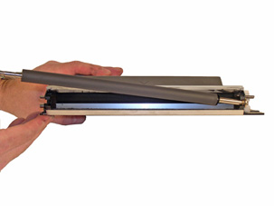
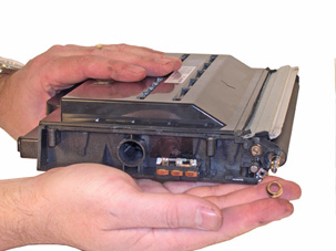
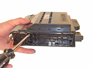
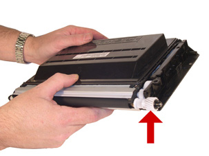
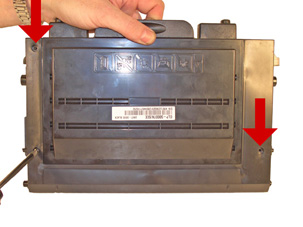
1) Remove the three screws from the top cover. See Figure 1 2) With the handle facing you, remove the screw from the left side. See Figure 2 3) Pry the cover away from the 2 tabs on the left side and lift the left side up slightly. See Figure 3 4)Pry the cover away from the two tabs on the right side. Lift the cover up and away from the cartridge. See Figures 4 & 5
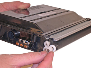
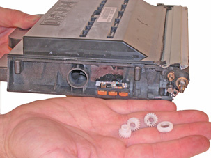
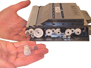
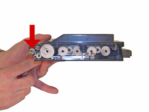
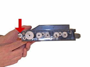
6) The black spring loaded reset gear may fall off as the plate is removed. This gear resets the printer when the cartridge is installed. New starter cartridges do not have this reset gear. Until they are available, the starter cartridges cannot be remanufactured. See Figure 5 &6 7) Remove the black plastic spacer from the developer roller shaft. See Figure 7 8) Remove the E-Ring, and small gear. See Figure 8
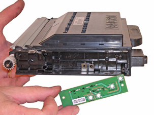
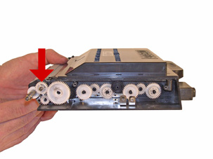
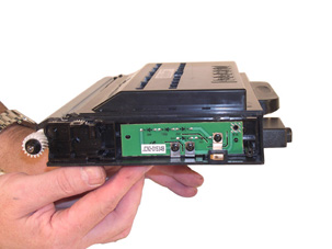
8) With the flat head screw driver, pry off the black end cap off the developer roller shaft on the small gear side of the cartridge. Remove the developer roller drive gear, and the two small gears next to it. Remove the white plastic bushing. See Figures 9, 10, & 11 9) On the large gear side, remove the three screws and contact from the Circuit board (PCB). See Figures 12 & 13.
10) Remove the PCB. See Figure 14. 11) Remove the two screws from the gear cover. Remove the cover by lifting up and away from the cartridge. See Figure 15 12) Pry the Black end cap off the developer roller shaft. See Figure 16
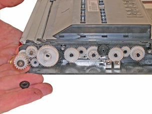
13) Remove the large developer roller gear See Figure 17 14) Remove the feed roller drive gear, flat washer and bushing from the cartridge. See Figures 18 & 19 15) On the small gear side, remove the E-ring from the developer roller shaft, and pry off the metal bushing. See Figures 20 & 21
18) Replace the chip. Make sure the chip you have is for the proper brand. Each brand has its own chip. (Lexmark, IBM, Dell) See Figure 21 19) If the foam cover is available, wrap the cartridge as indicated. This foam helps protect the developer roller from damage. Aftermarket covers are in development. See Figure 22 16) Remove the developer roller. The metal bushing on the opposite side is locked in place by a metal contact plate. See Figures 22 & 23 17) Clean the doctor blade and feed roller. Do not use any chemicals on the DB as they will damage the feed roller, and may react with the replacement toner. If there is a build up on the DB, carefully take the wood side of a cotton swan and rub it along the edge of the blade. Be very careful not to damage or bend the blade. See Figure 24
18) Wipe the developer roller down with a clean lint free cloth. It is also not advisable to use any chemicals here either. The residue from the chemicals may react with the replacement toner. Check with your vendor before using anything other than a clean cloth to clean these parts. 19) Install the developer roller, long shaft side to the large gear or PCB side. See Figure 25 20) On the small gear side, install the metal bushing and E-ring. You may have to tap the bushing in place to get access to the E-ring slot. See Figures 26 & 27 21) Install the plastic bushing, three gears and black end cap. See Figure 28
22) Install the two screws on the metal developer roller cover. See Figure 29 23) On the large gear side, make sure the metal bushing is still in place. If not press it back in. Install the plastic bushing. See Figures 30 & 31 24) Install the feed roller drive gear, spacer side towards the cartridge. See Figure 32
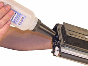
25) Install the gear train cover and two screws. See Figure 33 26) Install the large drive gear, flat washer, and black end cap. See Figure 34 27) Install the PCB three screws and contact. See Figure 35 28) Fill with the appropriate toner, and replace the fill cap. Remember, it is not a good idea to change the color of a cartridge. See Figure 36
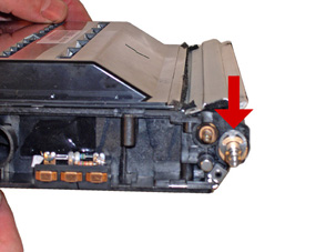
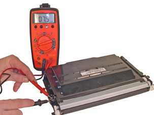
29) Check the two resistors if they are blown replace them. The inner is a 56 Ohm and the outer is a 7.5KOhm resistor. If the inner 56Ohm resistor is blown, it is important to replace it with a flame proof type. These resistors are designed to take a lot of heat with out burning. See Figure 37 30) Snap the top cover in place make sure the four tabs are locked in. See Figure 38 31) Install the three top screws and one side screw. See Figure 39
Demo Page With the printer ready, press and hold the Upper level button for 2 seconds. The upper level button is the one that has a curved arrow pointing up on it. The Demo page will print out Configuration Page With the printer ready, press the Menu button until you see Information on the bottom of the display. Press the Enter (asterisk) button to access the menu. Press the Enter button when Configuration appears on the bottom of the display. The Configuration page will print out. These machines have text error messages that appear on the display. There is no need to list them here. The one thing that may not be clear are LSU error messages. LSU stands for Laser Scanning Unit .
|