*Remanufacturing the Lexmark T640 Series Toner cartridge
0366
First introduced in July 2005, the Lexmark T640 series is based on the Lexmark T640 1200 dpi engine. Depending on the model, the print speed is from 30-50 pages per minute. As with all of Lexmark's new heavy duty machines these machines are loosely based on the older Optra S machines but these are much faster. Due to the speed and fuser characteristics, the toner is completely different and unique to this series.
The machines currently available based on the T640 engine are:
Lexmark T640
Lexmark T640dn
Lexmark T640n
Lexmark T640dtn
Lexmark T640tn
Lexmark T642
Lexmark T642dn
Lexmark T642dtn
Lexmark T642n
Lexmark T642tn
Lexmark T644
Lexmark T644dn
Lexmark T644dtn
Lexmark T644n
Lexmark T644tn
Unisys UDS 540-MRN
Unisys UDS 540-N11
Unisys UDS 544-N11
The following IBM machines are thought to be based on the T640 engine, but this could not be confirmed at this time (August 2005).
IBM InfoPrint 1532 Express
IBM InfoPrint 1552
IBM InfoPrint 1552n
IBM InfoPrint 1572
As with the T630 machines, these cartridges have ARD (Anti-Recycling devices) installed in the Prebate or Return Program cartridges that will not allow the cartridge to be used again until the chip board is replaced. As with other Lexmark cartridges, the Non-prebate or standard cartridges will work with out replacing the chips. Replacement chips are currently being worked on and at the time of this writing (July, 2005), are not available. They should be available as you read this.
Lexmark for the first time is releasing different cartridges for different areas of the world. The Americas are one region; Europe , the Middle East and Africa are another; and the Asia Pacific region is the last. We are in the process of investigating them but a guess is that the only difference between the cartridges is the chips. We have listed the error message given if the wrong region cartridge is used at the end of this article.
There seems to be quite a few different OEM chips worldwide on these cartridges. Lexmark has the different regions, as well as the different cartridges. Different manufacturers will have different chips, (IBM, Toshiba, Unisys, Dell) if they use this engine, and MICR cartridges will also have a dedicated chip. The MICR function is controlled by the chip, so make sure you have the correct chip if the cartridge is to go into a dedicated MICR machine like a Source technologies.
All that being said, these cartridges have a huge profit potential (See below). Even with the extra cost of the chip, andhaving to be careful what machine it goes into, and where that machine is located, they are more than worthwhile to do.
The Americas Lexmark Part numbers for these cartridges are as follows:
Return Program 6K* cartridge: 64015SA list $135.00**
Return Program 21K* cartridge: 64015HA, List $330.00**
Return Program 32K* cartridge: 64415XA, List $355.00** T644 Series only
Standard 6K* cartridge: 64035SA list $185.00**
Standard 21K* cartridge: 64035HA, List $380.00**
Standard 32K* cartridge: 64035XA, List $405.00** T644 Series only
The Europe , the Middle East and Africa Lexmark Part numbers for these cartridges are as follows:
Return Program 6K* cartridge: 64016SE
Return Program 21K* cartridge: 64016HE
Return Program 32K* cartridge: 64416XE (T644 Series only)
Standard 6K* cartridge: 64036SE
Standard 21K* cartridge: 64036HE
Standard 32K* cartridge: 64036XE (T644 Series only)
The Asia Pacific Region Lexmark Part numbers for these cartridges are as follows:
Return Program 6K* cartridge: 64017SR
Return Program 21K* cartridge: 64017HR
Return Program 32K* cartridge: 64417XR (T644 Series only)
Standard 6K* cartridge: 64037SR
Standard 21K* cartridge: 64037HR
Standard 32K* cartridge: 64037XR (T644 Series only)
* Yield based on ISO/IEC 19752
** List prices current as of August 2nd, 2005
There are also two label cartridges, the 64004HA, and the 64404XA. For Europe change the A to an E, for Asia change it to an R.
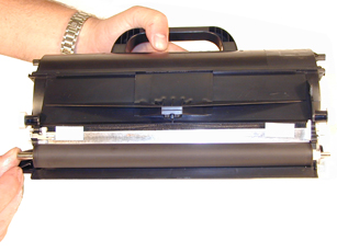
Figure 1 shows the shipping lock and foam wrap as it comes from Lexmark.
Lexmark only lists the extra high yield cartridges (32K) for the T644 series. The lower yield cartridges will give an unsupported cartridge error. The same will happen if the extra high yield cartridge is installed in the T640/T642 machines.
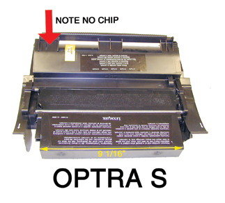
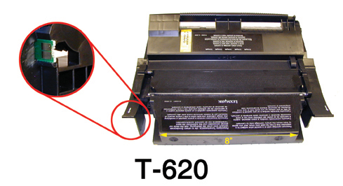
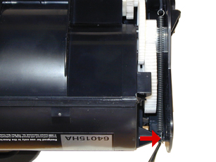
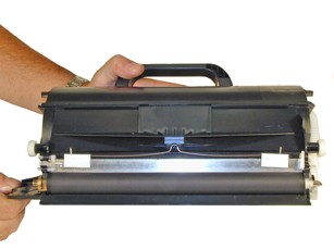
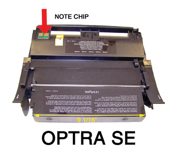
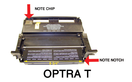
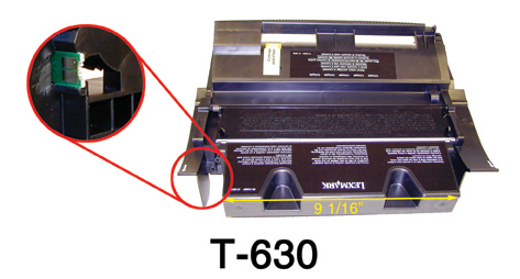
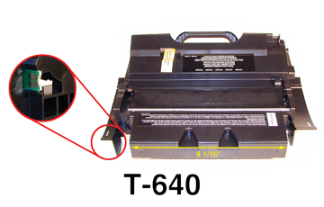
The T64x series of cartridges are different physically from the T630 in that they have a large handle in the back, and two large notches in the front edge of the waste chamber. Since all of the cartridges from the Optra S on are somewhat similar, we are showing all the different cartridge versions here. See Figure's 2-8
As with all the Optra cartridges based on this design, the Primary Charge Roller (PCR) is not in the cartridge, it's in the printer, and is rated for 300,000 pages. The Wiper Blade inside the cartridge has an external felt brush that keeps the PCR clean. Some of the starter cartridges have wiper blades without this felt. It is very important that the blade be replaced with a new one that has the felt. Otherwise a buildup on the PCR may occur.
It should also be noted that because of the play between the toner hopper and the OPC drum, a shipping lock should be installed in every cartridge. This holds true even if you are going to hand deliver the cartridge. This holds true for all the cartridges based on the Optra S design.
Machine Cartridge/troubleshooting as well as how to run test prints will be covered at the end of this article.
-
T640 Toner: Weights to be determined.
-
Drum padding powder (Kynar) Do NOT use Zinc Sterate
on these cartridges!
-
Cotton Swabs
-
Isopropyl Alcohol
-
Cotton Pads
-
Long life OPC Drum (Optional)(4059 Style)
-
Wiper Blade
-
Shipping Lock
-
Recovery Blade (4059 Style)
-
Retaining Blades
|
|
Figure 1 |
Figure 2 |
| 
|
|
Figure 3 |
Figure 4 |
|
|
Figure
5 |
Figure
6 |
|
 |
Figure
7 |
Figure 8 |
1) Vacuum the exterior of the toner cartridge. Be careful of the drum!
2) Place the cartridge on the bench drum side up (Label face down),with the toner supply towards you.
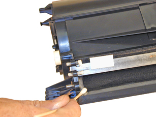
3) With a spring hook, remove the two springs from each end of the cartridge. See Figure 9
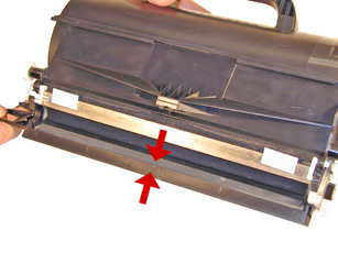
4) There are two plastic posts from the hopper that fit into the
cartridge shell. Pull the edge of the shell out to release the posts, and lift
up the hopper so that the posts are free. See Figure 10
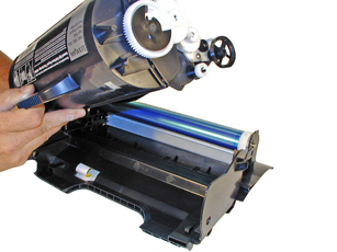
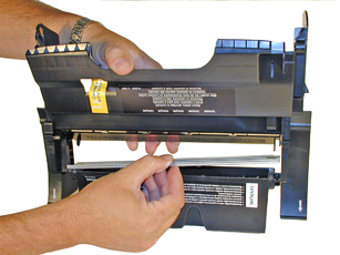
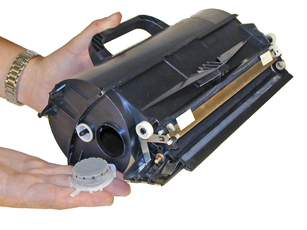
5) Slide the hopper to the right, and remove from the cartridge. Pull it out so that the large white bearing comes free. Place the hopper aside. See Figure 11
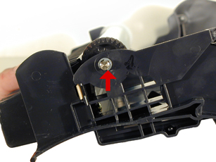
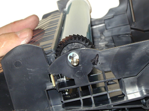
6) Remove E-Ring from the small white helical gear end of the drum axle. There is no need to remove the opposite E-ring. See Figure 12
|
|
Figure
9 |
Figure
10 |
|
|
|
Figure
11 |
Figure
12 |
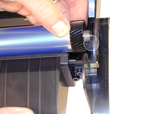
7) Slide the Drum Axle out of the cartridge. Hold the small helical gear while pulling it out so that the drum is not damaged in the process. Note the location of the small spring. See Figure's 13 & 14
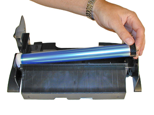
8) Gently lift the Drum up and out of the cartridge, if you are going to reuse the drum, place it in a light protected area. Be careful not to lose the spring, its' purpose is to keep the drum from rotating backwards. See Figure 15
9) Remove the Wiper Blade by removing the two screws on either end of the Wiper Blade. See Figure 16
|
|
Figure
13 |
Figure
14 |
|
|
|
Figure
15 |
Figure
16 |
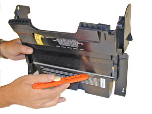
10) Place the cartridge so that the waste bin is face-up. Take a razor blade and cut the foam seal that runs along the back edge of the wiper blade to separate it from the cartridge. Make sure to cut along the plastic/foam, and not the blade. See Figure 17
11) Hold the cartridge so that it is up-right (Standing up with the waste bin on the table). With one hand, hold the laser shutter open, and with the other hand, remove the Wiper Blade. See Figure 18
NOTE: Unlike most of the other cartridges based on this design, the replacement cartridges do not have a wiper blade with a Cleaning Assembly. Time will tell if later cartridges will have them.
12) Make sure that the two end foams are clean and in their proper place See Figure 19
13) Pad the new Wiper Blade with Kynar padding powder, replace the blade and two screws into the cartridge. (Don't use Zinc Sterate on these cartridges! See Figure 20
|
|
Figure
17 |
Figure
18 |
|
|
|
Figure
19 |
|
14) Place a piece of clear tape along the edge of the Wiper Blade. If the tape does not stick well, the area should be cleaned with alcohol. It is very important to get a good seal with the tape, otherwise the cartridge will leak. Trim away any excess tape. See Figure 21
Be careful not to allow any tape into the laser port opening!
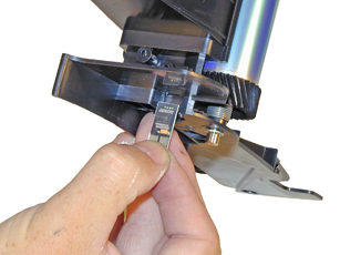
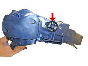
15) With a pair of needle nose pliers, gently pry off the Encoder Wheel. Make sure you pry it off from the center shaft so that the wheel does not become damaged. Place the wheel in a safe place. Remember, this wheel tells the cartridge what type of cartridge it is, Prebate or Non-Prebate. The chip is what tells the machine what type of yield the cartridge has. If this wheel becomes damaged, it must be replaced. See Figure 22
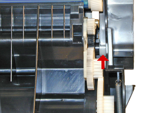
16) Remove the drive gear from the developer roller shaft. See Figure 23
|
|
Figure
20 |
Figure
21 |
|
|
|
Figure
22 |
Figure
23 |
17) Remove the Doctor Blade Spring by pressing down on the center of the spring. See Figure 24
18 Remove the developer roller cover by pulling out the left side, and sliding out the right from the pins. See Figures 25 & 26
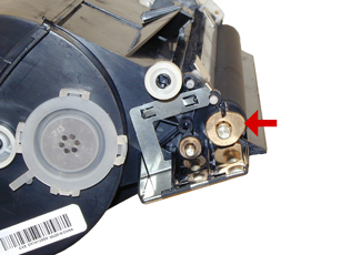
19) On the left (fill Plug) side of the Static Roller there is a small metal bushing, take a small screwdriver, and pry the bushing up so that the tab on the bushing is facing up. This will release the bushing, and Developer Roller. See Figure 27
|
|
Figure 24 |
Figure 25 |
|
|
|
Figure 26 |
Figure 27 |
20) Remove the Developer Roller. Note that the spacers are now clear instead of white. See Figures' 28 & 29
NOTE: Always remove the Doctor Blade Spring before removing the Developer Roller, failure to do this will cause the Doctor Blade to slide down from its original position and break the seal.
21) Remove the fill plug from the hopper. Pry the plug out from the base next to the hopper. The fill plug is also a breather cap. It is best to remove both sections at once and to clean them from the outside. These plugs tend to leak if they have been separated. See Figure 30
22) Vacuum the Toner Hopper clean.
23) With a cotton swab dipped in alcohol, clean the Developer Roller seals located on either end of the static roller section. These seals are made of a white plastic. Also clean the electrical contact that touches the Developer Roller shaft. See Figure 31
|
|
Figure 28 |
Figure 29 |
|
|
|
Figure 30 |
Figure 31 |
24) Carefully vacuum or blow off the Developer Roller, Be careful not to touch the roller with your hands, or to damage this roller in any way.
25) Inspect the inner and outer retaining blades (Black Mylar). If they are bent in any way, they must be replaced as they will leak. See Figure 32
26) Place the keyed end of the Static Roller into the cartridge, and install the roller. See Figures 33 & 34
27) Install the bushing onto the developer roller shaft, turning it so that the tab is facing down. This will lock the roller in place. See Figure 35
|
|
Figure 32 |
Figure 33 |
|
|
|
Figure 34 |
Figure 35 |
28) Install the Doctor Blade Spring. See Figure 36
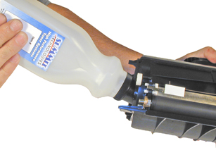
29) Fill the hopper with the appropriate amount of toner. Remember, the amount of toner that can be placed in the cartridge is controlled by the chip . Install the Fill Plug. See Figure 37
30) Install the developer roller cover. Make sure the pins are aligned correctly in the cover. See Figures 38 & 39
|
|
Figure 36 |
Figure 37 |
|
|
|
Figure 38 |
Figure 39 |
31) Install the Encoder Wheel
32) Take the OPC drum and lightly coat with the Drum Padding Powder,(Kynar). Do NOT use DPP (Zinc Sterate), this powder will ruin the wiper blade.
33) Place the OPC Drum into the cartridge with the small helical gear on the NON-Contact side of the cartridge. Make sure that the spring is in the proper position! See Figure 40
34) Install the Drum Axle pin into the small white gear side of the drum.
The Axle must be installed this way to prevent the axle from bending and damaging the drum ground contact located inside the drum. See Figure 41
35) Install the E-Ring on the end of the axle. See Figure 42
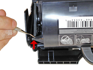
36) Remove the old chip with a pair of pliers, and install the new chip. The chip will just pull out, and slide back in. There are a few different physical versions of the aftermarket chips. Check with your supplier for the correct installation. See Figure 43
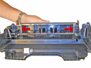
37) Take the Toner Hopper and install it left side first. Make sure that the left side post and the white bearing are in their proper slot. See Figure 44
|
|
Figure 41 |
Figure 42 |
|
|
|
Figure 43 |
Figure 44 |
38) On the right side of the cartridge, pull the cartridge shell out so that the right side post falls into its slot. See Figure 45
39) With the spring hook, replace both springs on to the Toner Supply Chamber. See Figure 46
40) Re-install the Developer Roller drive gear. See Figure 47
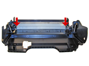
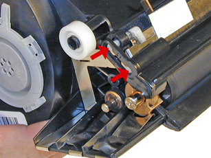
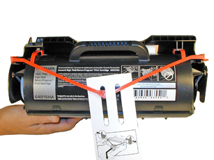
41) A shipping lock must now be installed. This lock should be used even if you are going to hand deliver the cartridge. It will prevent the toner hopper from coming in contact with the OPC Drum, and causing damage to either the Drum or the Developer Roller. Press the two red tabs into the sides of the cartridge as indicated in the picture supplied with the lock. See Figure 48
|
|
Figure 45 |
Figure 46 |
|
|
|
Figure 47 |
Figure 48 |
Cartridge Repetitive defect chart:
OPC Drum: 94mm
Developer Roller: 62mm
PCR (In machine) 38mm
Dirty Primary Charge roller ; Located inside the PRINTER, this will show on the test page as vertical gray streaks down the page, or as a gray background throughout the page.
Damaged PCR (In Machine): This will show as small marks that repeat 38mm
Damaged Developer Roller : This will show as small marks that repeat 62mm.
Scratched drum : this is shown by a very thin, perfectly straight line that runs from the top to the bottom of the test page.
Chipped drum: This will show as a dot or series of dots that repeat 2 times per page. Any drum defects will repeat 3 times per page based on the drum circumference of 94mm
Light damaged drum : This will show up as a shaded area on the test print that should be white. Again this will repeat 3 times per page.
Bad wiper blade: This will show as either a gray line approximately 1/8" thick or as shading across the entire page. In either case there will be a film of toner on the drum surface.
Weak Dr. Blade Spring: This will usually show as shaded areas on one or both sides of the page.
Machine Error Codes:
Most of the error messages appear to be in text, and do not need an explanation. No numeric messages are listed in the user guide except for the following:
42.xy This is a cartridge region mismatch. The x = the printer region, and they = the cartridge region. Both must match each other.
Region codes are as follows: (See text at beginning of article.)
0 = Worldwide
1 = Americas
2 = Europe region
3 = Asia region
9 = undefined
Taking Test Prints:
Printer menu:Press the MENU key (has a picture of a key on it)
Press the DOWN ARROW until the check mark is next to REPORTS
Press the Check mark (Select) button
Press the DOWN ARROW until the check mark is next to MENU SETTINGS
Press the Check mark (Select) button
Font Sample:
Press the MENU key (has a picture of a key on it)
Press the DOWN ARROW until the check mark is next to REPORTS
Press the Check mark (Select) button
Press the DOWN ARROW until the check mark is next to PRINT FONTS
Press the Check mark (Select) button
Press the DOWN ARROW until the check mark is next to PCL FONTS, POSTSCRIPT FONTS, or PPDS FONTS
Press the Check mark (Select) button
Changing the Printer Density:
Press the MENU key (has a picture of a key on it)
Press the DOWN ARROW until the check mark is next to QUALITY
Press the Check mark (Select) button
Press the DOWN ARROW until the check mark is next to TONER DARKNESS
Press the Check mark (Select) button
Choose a number between 1 and 10. 10 is the darkest (8 is default)
In addition to changing the density, the quality menu also allows you to change the resolution-600dpi default, the brightness-0 default, (adjusts the gray value of pictures), and the Contrast-0 default (adjusts the contrast of pictures)
* These chips are designed to work on Non-Prebate, (Non-return) cartridges only
|